Greensmaster Flex 21Groomer (Model 04204) (Rev. B) Page 9 – 14
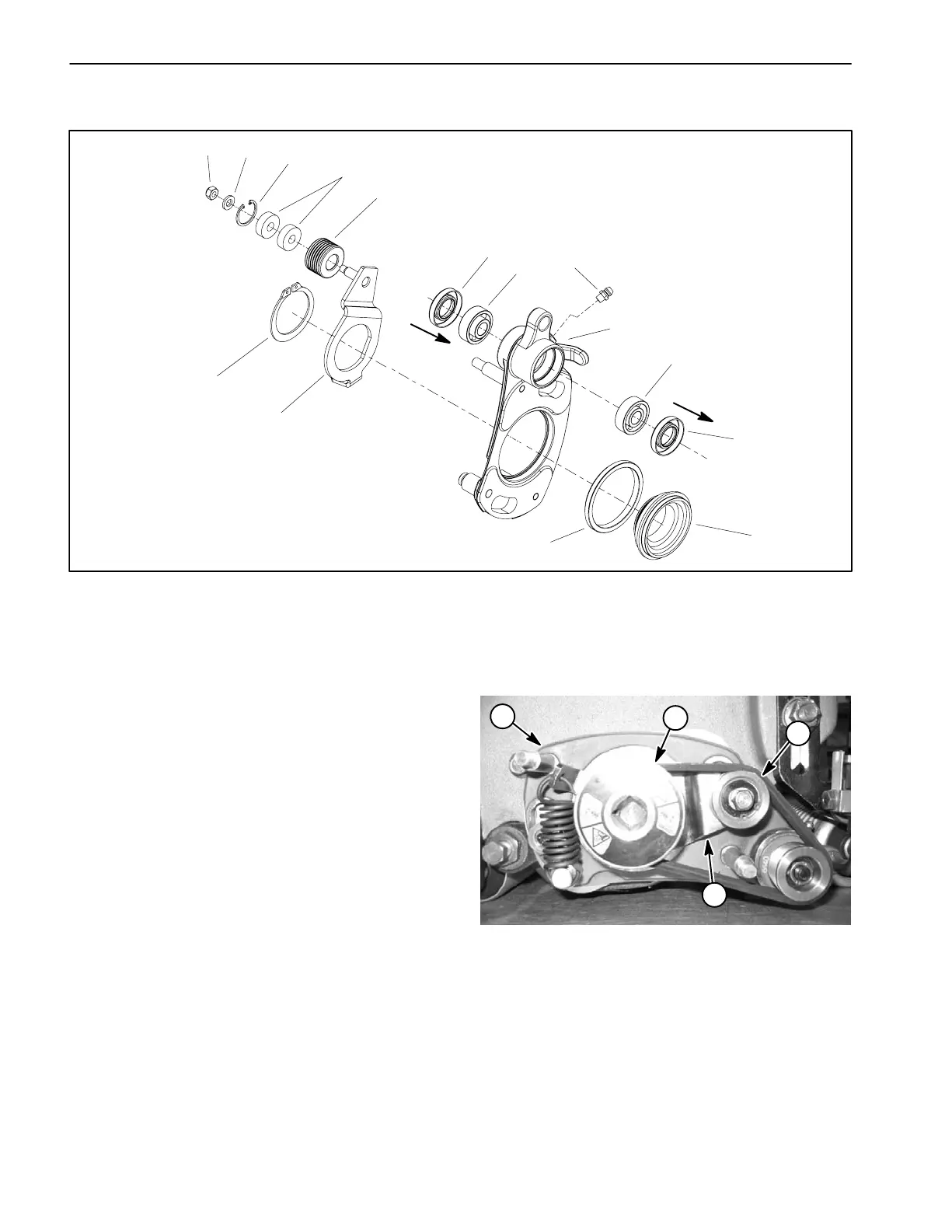
Idler Assembly
Figure 15
1. Lock nut
2. Flat washer
3. Retaining ring
4. Idler bearing
5. Idler pulley
6. Seal
7. Bearing
8. Grease fitting
9. RH side plate
10. Pivot hub
11. Bushing
12. Idler bracket
13. Retaining ring
3
5
2
6
4
7
12
13
11
1
6
7
9
10
8
Seal lip
Seal lip
The right side plate assembly of the Flex 21 groomer kit
incorporates the idler system for tensioning the groomer
drive belt. The idler system uses a spring to maintain
proper belt tension.
Removal
1. Remove groomer belt cover, drive belt and drive
pulley from right side of mower (see Groomer Reel Re-
moval in this section).
2. Using Figures 15 and 16 as guides, remove idler
bracket, idler pulley and/or idler bearings for service as
needed.
Installation
1. Reassemble components using Figures 15 and 16
as guides.
NOTE: When properly installed, the idler pulley should
move freely from side to side on the idler bracket pin.
2. Install drive pulley, drive belt and belt cover to right
side of mower (see Groomer Reel Installation in this sec-
tion).
1. RH side plate
2. Drive pulley
3. Idler bracket
4. Idler pulley w/bearings
Figure 16
1
2
3
4
 Loading...


