Rev. C
Greensmaster Flex 21
Page 5 – 8
Electrical System
Service and Repairs
NOTE: See the Kawasaki FE120 Service Manual in
Chapter 3 – Engine for more engine component repair
information.
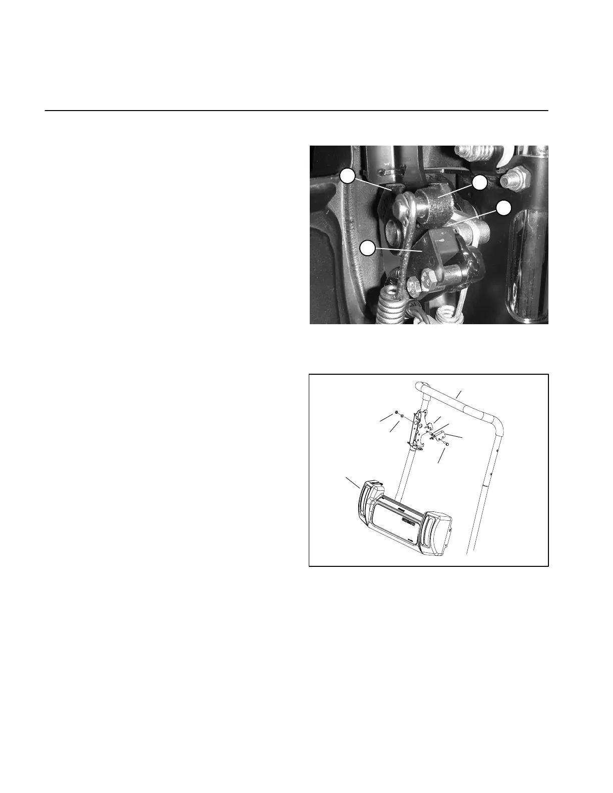
Interlock Switch
Adjustment
1. Make sure the engine is OFF and the traction lever
is in the NEUTRAL position.
2. Loosen interlock switch mounting fasteners.
3. Hold traction lever against the neutral stop (Fig. 6).
4. Place a .032“ (.8 mm) thick shim between the traction
lever and the interlock switch.
5. Tighten interlock switch mounting fasteners. Re-
check gap. The traction lever must not contact the
switch.
6. Engage traction lever and verify that the switch
opens (no continuity).
Removal
1. Disconnect switch from the wires leading from the In-
terlock module.
2. Remove fasteners and spacers that mount switch to
control bracket on handle (Fig. 7). Remove switch from
bracket.
Installation
1. Position switch to control bracket with fasteners and
spacers.
2. Adjust interlock switch (see Adjustment above) as
necessary.
3. Connect switch to wires from the interlock module.
1. Traction lever
2. Neutral sto
3. Interlock switch
4. Clearance
Figure 6
1
4
3
2
1. Interlock switch
2. Control bracket
3. Handle
4. Cap screw
5. Spacer
6. Flat washer (early units)
7. Locking nut
8. Console
Figure 7
5
3
1
2
6
4
7
8
 Loading...


