4.Rollthedeckandframeintopositionandinstallthe
5bolts(3/4inch),washersandnutsthatconnectthe
deckframetotherearframe.
5.Removethemountingbracketandsupporttubetogain
accesstotheboltsontheright-handside(Figure9).
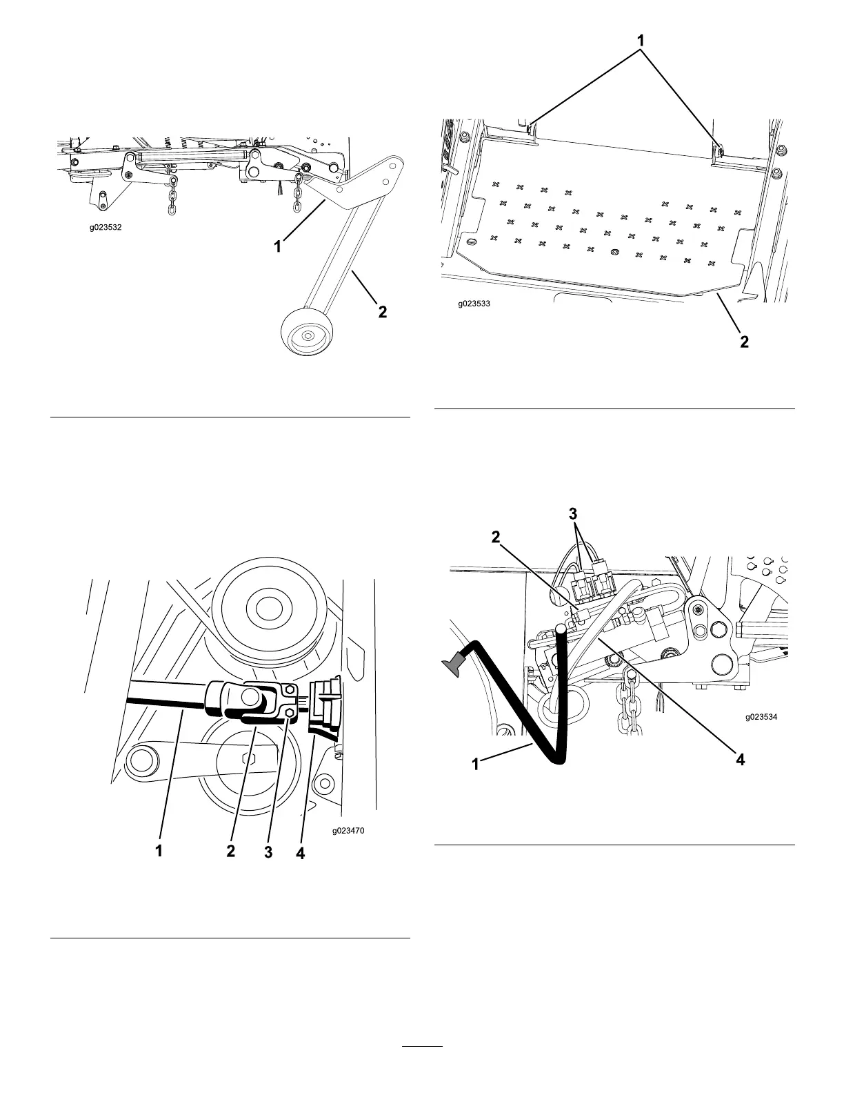
Figure9
1.Mountingbracket
2.Supporttube
6.Torquetheboltsto265ft-lbs(359N-m).
7.Removetheclevispinsandthe8mm(5/16
inch)self-tappingscrewpinretainerssecuringthe
vertical-tubesupportassembliestotherearofthedeck
frame.
8.Slidethedriveshaftontothegearboxshaft(Figure10).
Figure10
1.Driveshaft3.Bolt(5/16inch)
2.Rollpin
4.Gearbox
9.Installtherollpin,andtorquetheboltsto175to225
inch-lbs(20to25N-m).
10.Installtheoorplateusingthe2clevispins(Figure11).
Figure11
1.Clevispins
2.Floorplate
11.Routeandconnectthehydraulic-pressurehoseand
tankhosetothecontrolvalve(Figure12).
12.Connecttheelectricalwirestotheelectricalconnectors
(Figure12).
Figure12
1.Tankhose3.Electricalconnectors
2.Controlvalve
4.Pressurehose
13.Installtherearofthedeck-liftcylinderontothepivot
pinandsecureitwiththeretainingring(Figure13).
14.Securethefrontoftheliftcylindertothemowerframe
withthecylinderpinandscrew(Figure13).
19