96).Increaseordecreasethecompressor
belttensionandtightenthebolt.Checkthe
deectionofthebeltagaintoensurethatthe
tensioniscorrect.
Re-tensioningtheBlade
DriveBelts
ServiceInterval:Aftertherst10hours
Every50hours
Checktheconditionandtensionofthecuttingunit
drivebeltsinitiallyafter10hoursofoperationand
every50operatinghoursthereafter.
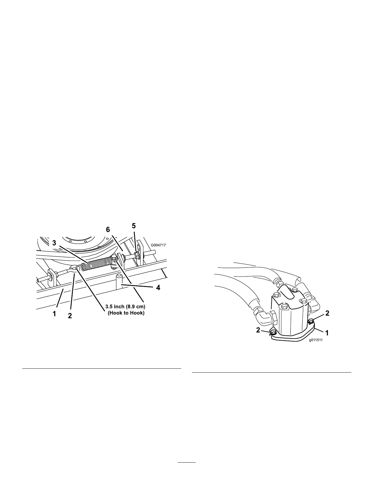
Whenproperlytensioned,theextensionspring(hook
tohook)measurementshouldbeapproximately8.9
cm±.63cm(3.50±.25inch)(inside).Oncethe
correctspringtensionisattained,adjustthestop
bolt(carriagebolt)untilthereisapproximately.32
cm±.152/.000cm(.125+.060/-.000inch)clearance
betweentheheadoftheboltandtheidlerarm(Figure
97).
Note:Makesurethebeltispositionedonthespring
sideofthebeltguide(Figure97).
g004717
Figure97
1.Belt4.Beltguide
2.Eyebolt5.Flangenut
3.Extensionspring
6.Stopbolt
ReplacingtheBladeDrive
Belt
ServiceInterval:Every800hours
Thebladedrivebelt,tensionedbythespringloaded
idlerpulley,isverydurable.However,aftermany
hoursofuse,thebeltwillshowsignsofwear.Signs
ofawornbeltare:squealingwhenbeltisrotating,
bladesslippingwhencuttinggrass,frayededges,
burnmarksandcracks.Replacethebeltifanyof
theseconditionsareevident.
1.Lowerthecuttingunittotheshopoor.Remove
thebeltcoversfromthetopofthecuttingunit
andsetthecoversaside.
2.Loosentheeyeboltallowingtheremovalofthe
extensionspring(Figure97).
3.Loosentheangenutsecuringthestopbolt
tothemountingtab.Backoffthenutenough
toallowtheidlerarmtopassbythestopbolt
(Figure97).Movetheidlerpulleyawayfromthe
belttoreleasebelttension.
Note:Ifthestopboltiseverremovedfromthe
mountingtab,makesureitisreinstalledinthe
holethatalignsthestopboltheadwiththeidler
arm.
4.Removetheboltssecuringthehydraulicmotor
tothecuttingunit(Figure98).Liftthemotoroff
ofthecuttingunitandlayitontopofthecutting
unit.
g011511
Figure98
1.Hydraulicmotor2.Mountingbolts
5.Removetheoldbeltfromaroundthespindle
pulleysandidlerpulley.
6.Routethenewbeltaroundthespindlepulleys
andidlerpulleyassembly.
7.Positionthehydraulicmotoronthecutting
unitafterroutingthebeltaroundthepulleys.
Mountthemotortothecuttingunitwiththebolts
previouslyremoved.
63