5.Measurethedistancebetweenthe2rearfaces
ofthefronttiresasshowninFigure83.
Recordthefrontmeasurementhere
.
Note:Thefrontmeasurementshouldbe6.4to
12.7mm(1/4to1/2inch)largerthantherear
measurement.
6.Ifthefrontmeasurementissmallerthan6.4mm
(1/4inch)orlargerthan12.7mm(1/2inch),
adjustmenttherodendsforthesteeringlinkage
asfollows:
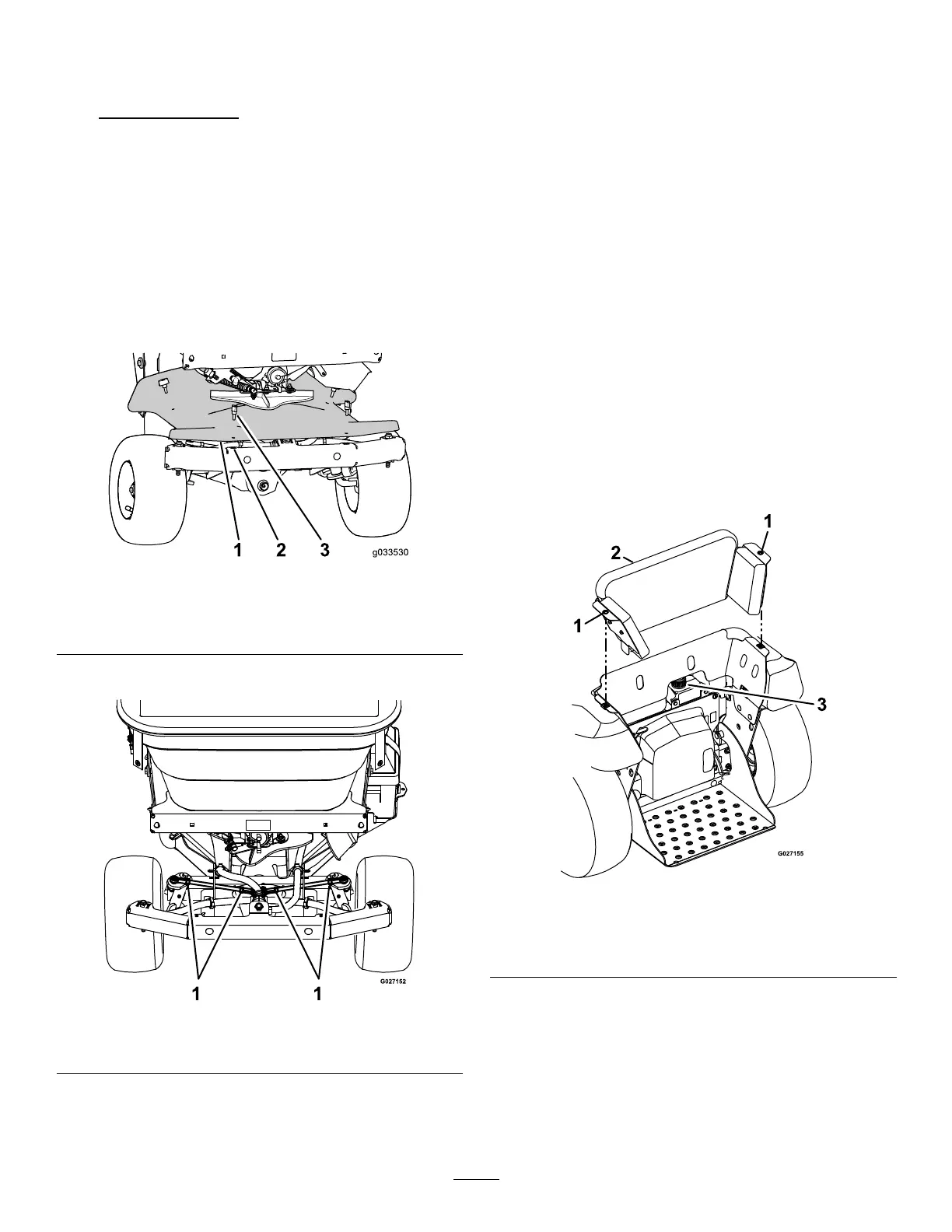
A.Removethe4thumbscrewsthatsecure
thefrontcover(belowtheimpeller)tothe
chassisandremovethecover(Figure84).
g033530
Figure84
1.Forwardcover3.Thumbscrew
2.Clipnut
B.Loosenthejamnutsattherodends.
g027152
Figure85
1.Jamnuts
C.Rotatethesteeringrodtolengthenor
shortenthelinkage.Adjustboththeleftand
rightsteeringlinkagesequally.
Note:Thefactorycenter-to-center
distancebetweentheball-jointrodends
atthesteeringlinkageis23.3cm(9.21
inches).
D.Tightenthejamnuts.
E.Aligntheholesinthefrontcoverwiththe
clipnutsinthechassisandsecurethecover
withthe4thumbnutsthatyouremovedin
A.
7.Removetheboltsthatyouinstalledinstep3
fromthecontrolcolumnandsteeringcontrol.
ServicingtheTransaxle
ServiceInterval:Every50hours
TransaxleOilType:T oro®HYPR-OIL™500
hydraulicoilorMobil®115W-50
1.Preparethemachineformaintenance;referto
PreparingtheMachine(page51).
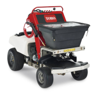
2.Rotatecounterclockwisethe2quarter-turn
fastenersthatsecurethekneepadtothe
chassisofthemachine(Figure86).
g027155
Figure86
1.Quickreleasescrews3.Oilexpansiontank
2.Kneepad
3.Liftthekneepadupandrearwardslightlyand
removethepadfromthemachine(Figure86).
4.Cleanareaarounduid-expansiontankand
removecap(Figure86).
5.Checktheuidlevelintheexpansiontank.
Note:Theuid-levelcoverthebottomportin
tank
63