19
Schedule Settings for AUX SCHEDULE
e Aux Schedules are highly simplied programs that can be enabled to work in addition to Schedules A, B, and C. Aux Schedules are
assigned to a single valve or relay, have a single start time, and use the Weekday Schedule type.
Aux1 can operate a valve or relay which is hard wired to one of the valve terminals. Aux2 and Aux3 are wireless, and require the use of the
Smart Connect (A-EVO-SC) wireless module, and the Wireless Auxiliary Relay (A-EVO-AR).
Set Schedule Status – Select the schedule’s mode. Place it in ENABLED (Active) or DISABLED (OFF).
AUX 1
STATUS ENABLED
ACTIVE DAYS
START OFF
RUNTIME OFF
VALVE VALVE1
ERASE SCHEDULE
Step 1 – Use the Up or Down arrows to navigate to STATUS, then press SELECT .
Step 2 – Use the Up or Down arrows to ENABLE (turn on) or DISABLE (turn o) the schedule. Press
SELECT to save.
Set Active Day – Select the days that the Auxiliary Schedule can be activated.
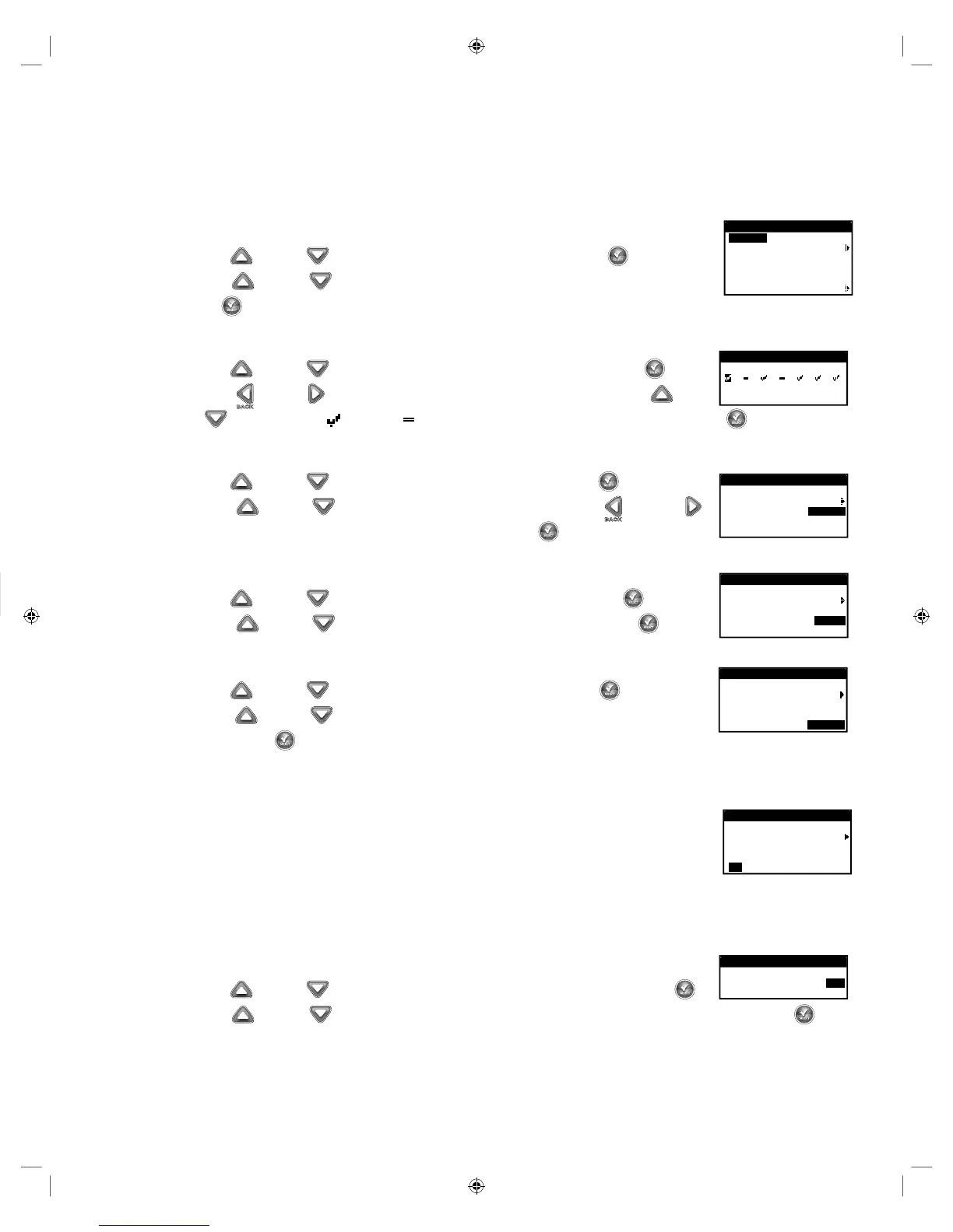
Step 1 – Use the Up or Down arrows to navigate to ACTIVE DAYS, then press SELECT .
AUX 1
S M T W T F S
TODAY IS THURSDAY
Step 2 – Use the Left or Right arrows to navigate within the days of the week. Use the Up or
Down arrows to activate or turn o Auxiliary. Repeat for all days of the week. Press SELECT when nished.
Set Start – Set the start time that the Auxiliary Schedule is activated.
Step 1 – Use the Up or Down arrows to navigate to START, then press SELECT .
AUX 1
STATUS ENABLED
ACTIVE DAYS
START 07:30AM
RUNTIME OFF
VALVE VALVE1
Step 2 – Press the Up or Down arrows to enter the desired start time. Use the Left and Right
arrows to navigate between Hours and Minutes, then press SELECT when nished.
Set Runtime – Set the duration that the Auxiliary Schedule is activate.
Step 1 – Use the Up or Down arrows to navigate to RUNTIME, then press SELECT .
AUX 1
STATUS ENABLED
ACTIVE DAYS
START 07:30AM
RUNTIME 04:30
VALVE VALVE1
Step 2 – Press the Up or Down arrows to enter the desired runtime, then press SELECT .
Select Valve – (AUX1 Only) Assign a valve terminal to AUX1.
Step 1 – Use the Up or Down arrows to navigate to VALVE, then press SELECT .
AUX 1
STATUS ENABLED
ACTIVE DAYS
START 07:30AM
RUNTIME 04:30
VALVE VALVE1
Step 2 – Press the Up or Down arrows to assign a valve terminal to the auxiliary schedule,
then press SELECT .
Select Device – (AUX2 and AUX3 Only) Wireless Auxiliary function works in conjunction with Smart Connect Wireless module
(A-EVO-SC) and EVOLUTION
®
Auxiliary Relay (A-EVO-AR).
In order to communicate with the wireless auxiliary relays, the EVOLUTION
®
AG controller must be equipped
AUX 2
STATUS ENABLED
ACTIVE DAYS
START 08:00AM
RUNTIME 02:00
ID 94 73 00
with Smart Connect module. To connect the Smart Connect module, simply plug the module to the backside of
the EVOLUTION
®
AG’s timing mechanism. See Smart Connect’s installation instructions.
To communicate with the wireless auxiliary relay, you must add the device to the controller’s device list.
See ADD/REMOVE DEVICE/AUXILIARY section for details.
Once the wireless auxiliary relay has been added into the AUX2 or AUX3 schedule, the device’s ID number will be displayed in the
ADVANCED/SCHEDULE DETAILS/AUX2 (OR AUX3).
Erase Auxiliary Schedule
Step 1 – Use the Up or Down arrows to navigate to ERASE SCHEDULE, then press SELECT .
ERASE SCHEDULE
ARE YOU SURE? YES
Step 2 – Use the Up or Down arrows to YES to proceed to erase the schedule or NO to cancel, then press SELECT .
Erase Schedule
– Reset the selected schedule. e schedule’s status will be set to DISABLED (except for schedule A, it remains
ENABLED) and the schedule TYPE set to WEEKDAYS. All other settings within the schedule will be set to OFF.
Step 1 – While in the ADVANCED/SCHEDULE DETAILS menu, use the Up
or Down arrows to select the Schedule you
want to edit. Press SELECT .
Step 2 – Use the Up
or Down arrows to navigate to ERASE SCHEDULE, then Press SELECT .
ERASE SCHEDULE
ARE YOU SURE? NO
Step 3 – Use the Up or Down arrows to Yes to proceed to erase the schedule or No to cancel, then press SELECT .
Set MV/Pump Delay – Set a wait time between activating the master valve or pump, and activating the rst valve in the schedule.
is delay is usually used to allow the system enough time to build pressure for proper operation, or to ll the irrigation piping system with
water.
Step 1 – While in the ADVANCED/SCHEDULE DETAILS menu, use the Up
or Down arrows to select the Schedule you
want to edit. Press SELECT .
Step 2 – Use the Up or Down arrows to navigate to MV/PUMP DELAY. Press SELECT .
SCHEDULE A
ERASE SCHEDULE
MV/PUMP DELAY 00:10
VALVE DELAY OFF
Step 3 – Use the Up or Down arrows to adjust the delay time as necessary. Press SELECT .
Set Valve Delay – Set a wait time after a valve closes and before another valve is activated. is delay is commonly used when the
system is being fed by a well. e delay allows the well time to recharge. Valve delay can be set with a maximum duration of 30 minutes.
Step 1 – While in the ADVANCED/SCHEDULE DETAILS menu, use the Up
or Down arrows to select the Schedule you
want to edit. Press SELECT .
Step 2 – Use the Up or Down arrows to navigate to VALVE DELAY. Press SELECT .
SCHEDULE A
MV/PUMP DELAY OFF
VALVE DELAY 00:10
MV/PUMP IN DELAY OFF
Step 3 – Use the Up or Down arrows to adjust the delay time as necessary. e delay can be set
between 10 seconds to 30 minutes in 10-second increments. Press SELECT .
Set MV/Pump In Delay – Set whether the master valve or pump is active during valve delays. e default is set to OFF.
Step 1 – While in the ADVANCED/SCHEDULE DETAILS menu, use the Up or Down arrows to select the Schedule you
want to edit. Press SELECT .
Step 2 – Use the Up
or Down arrows to navigate to MV/PUMP IN DELAY. Press SELECT .
SCHEDULE A
MV/PUMP DELAY OFF
VALVE DELAY OFF
MV/PUMP IN DELAY ON
Step 3 – Use the Up or Down arrows to set the MV/Pump In Delay to ON or OFF during valve
delays. Press SELECT .
Note: is function is used when a well needs time to recover between valve openings. For example, a schedule includes Valve 1 and
Valve 2. A VALVE DELAY of 10 minutes has been programmed. Valve 1 opens, irrigates, and closes. e 10 minute Valve Delay begins.
e grower’s desire in this example is for the pump to be o during this 10 minutes before Valve 2 opens to allow the well to recover, so he
would set the MV/PUMP IN DELAY to OFF. is ensures that the MV/Pump relay will be o during the 10 minutes of VALVE DELAY
between Valve 1 and Valve 2.