Cooling System
Maintenance
Cleaning the Air-Intake
Screen
Service Interval : Before each use or daily
Before each use, remove any buildup of grass, dirt,
or other debris from the cylinder and cylinder-head
cooling ns, air-intake screen on the ywheel end,
and the carburetor-governor levers and linkage. This
helps ensure adequate cooling of the engine and the
correct engine speed, and it reduces the possibility of
overheating or mechanical damage to the engine.
Cleaning the Cooling
System
Service Interval : Every 100 hours —Check and
clean the engine cooling ns and
shrouds (more often in dirty or dusty
conditions).
1. Park the machine on a level surface, disengage
the PT O, and engage the parking brake.
2. Shut of f the engine, remove the key , and wait
for all moving parts to stop before leaving the
operating position.
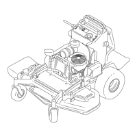
3. Remove the air-intake screen and fan housing
( Figure 64 ).
4. Clean the debris and grass from the engine
parts.
5. Install the air-intake screen and fan housing
( Figure 64 ).
g031343
Figure 64
1. Guard and engine
air-intake screen
2. Fan housing
Brake Maintenance
T esting the Parking Brake
Service Interval : Before each use or daily
Before each use, test the parking brake on both a
level surface and slope.
Always engage the parking brake when you stop the
machine or leave it unattended. If the parking brake
does not hold securely , adjust it.
1. Disengage the PT O and engage the parking
brake
2. Shut of f the engine, remove the key , and wait
for all moving parts to stop before leaving the
operating position.
3. Disengage the parking brake.
4. Engage the brake lever and ensure that the
machine does not move.
5. Adjust the brake if needed.
Adjusting the Brakes
1. Remove the fuel tank; refer to Removing the
Fuel T ank ( page 36 ) .
2. Loosen the bolt on the cable clamp on the left
side of the machine.
g031396
Figure 65
1. Cable
3. Bolt and nut
2. Cable clamp
3. Pull down on the cables until they are taut.
4. T ighten the nut.
5. Install the fuel tank, cross bracket, and cushion.
44
 Loading...


