4. Remove the hydraulic-reservoir cap.
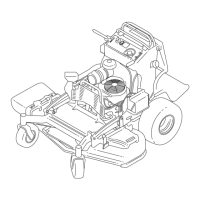
5. Locate the drain plug in the bottom of each
transmission and place a drain pan under the
plugs ( Figure 72 ).
g268090
Figure 72
1. Drain plug
2. Hydraulic lter
6. Remove the drain plugs.
7. Allow the hydraulic uid to fully drain from the
machine.
8. Remove the hydraulic lter cap and lter from
each transmission.
9. Install new hydraulic lters with the spring side
facing out and install the lter caps.
10. Install the drain plugs and torque to 22 to 27
N∙m (16 to 20 ft-lb).
1 1. Loosen the vent plug in each transmission so
that it is loose and wobbles ( Figure 73 ).
Note: This allows air to escape the hydraulic
system as you add hydraulic uid.
g031544
Figure 73
Left transmission shown
1. V ent plug
12. Slowly add uid to the hydraulic tank until it
starts to come out 1 of the vent plugs.
Important: Use the uid specied in
Hydraulic System Specications ( page 48 ) or
equivalent. Other uids could cause system
damage.
Important: Monitor the level of uid in the
hydraulic tank so that you do not overll it.
13. T ighten the vent plugs.
14. Install the hydraulic-tank cap.
15. Install the fuel tank.
16. Start the engine and let it run for about 2 minutes
to purge air from the system.
17. Shut of f the engine and check for leaks.
Note: If 1 or both wheels do not drive, refer to
Bleeding the Hydraulic System ( page 49 ) .
Bleeding the Hydraulic
System
The traction system is self-bleeding, however , it may
be necessary to bleed the system if uid is changed
or after work is performed on the system.
1. Park the machine on a level surface, disengage
the PT O, and engage the parking brake.
2. Shut of f the engine, remove the key , and wait
for all moving parts to stop before leaving the
operating position.
3. Raise the rear of the machine onto jack stands
high enough to raise the drive wheels of f the
ground.
4. Start the engine and move the throttle control to
the idle position.
Note: If the drive wheel does not rotate, assist
the purging of the system by carefully rotating
the tire in the forward direction.
5. Check the hydraulic uid level as it drops, and
add uid as required to maintain the proper level.
6. Repeat this procedure for the opposite wheel.
49
 Loading...


