g312028
Figure7
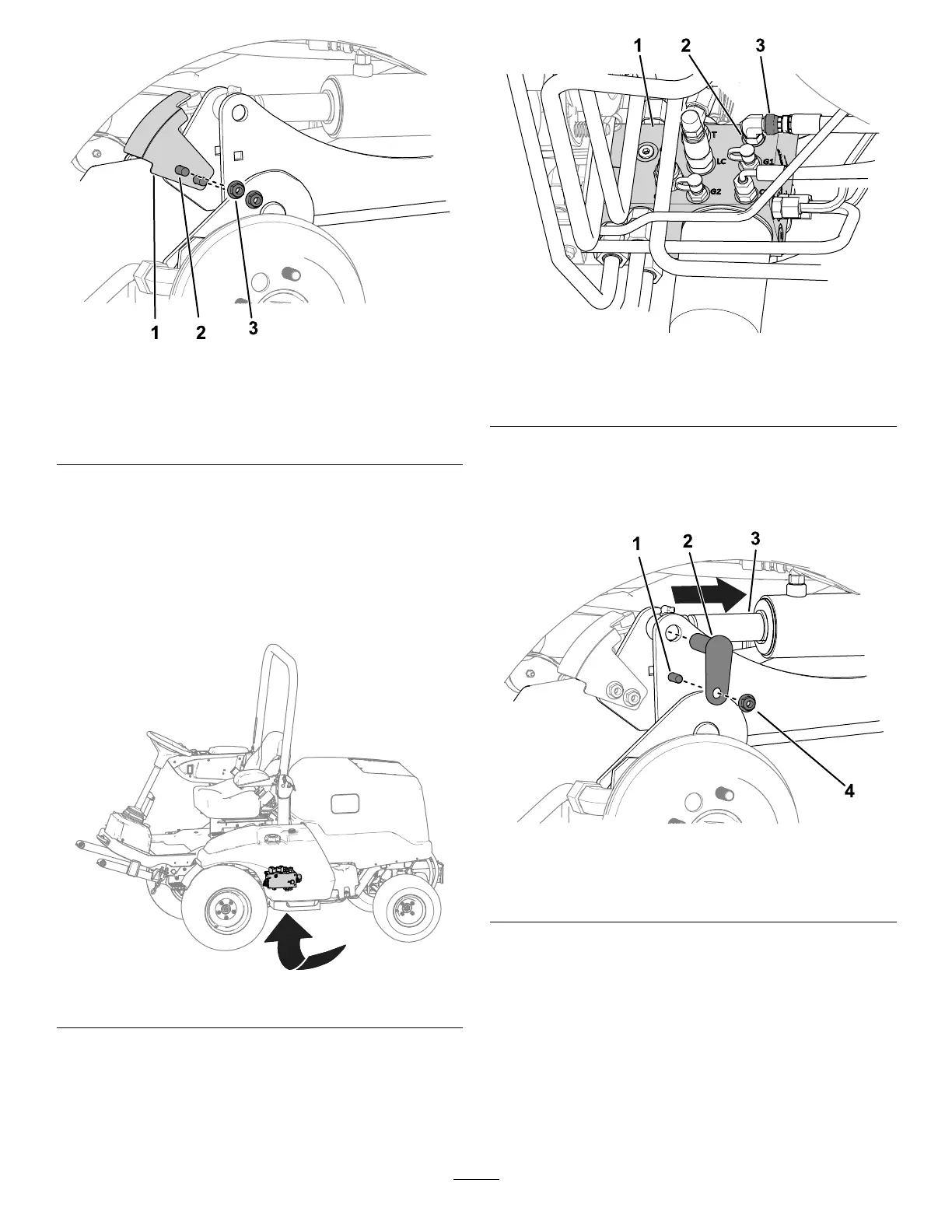
Rightsideshown.
1.Sensorbracket3.Nut(3/8inch)
2.Carriagebolt
6.Performthefollowingstepstosecurethe
hydrauliccylinderstotheliftarms:
A.Placeadrainpanunderthehydraulic
manifold(showninFigure8).
Note:Asmallamountofhydraulicuidwill
needtobebledinordertomanuallyretract
theliftcylinders.
g299920
Figure8
B.Loosenthehoseswivelnutconnectedto
portC1ofthehydraulicmanifold(Figure9).
g312025
Figure9
1.Manifold
3.Hoseswivelnut
2.PortC1
C.Useadriftpunchtoalignthecylinderrod
holeswiththelift-armholes(Figure10).
Note:Fullyraisetheliftarmtohelpwith
thealignment.
g312026
Figure10
1.Bolt(3/8x1-1/4inches)3.Cylinderrod
2.Smallpin4.Nut(3/8inch)
D.Use2bolts(3/8x1-1/4inches),2nuts(3/8
inch),and2smallpinstosecurethelift
armstothecylinders(Figure10).
E.TorquethehoseswivelnutonportC1
(Figure9)to41N∙m(30ft-lb).
Note:Youcanuseabackupwrenchto
preventthehosefromtwisting.
7.Greasetheattachmentpinjointsandlift-arm
pinjoints;refertoGreasingtheBearingsand
Bushings(page42).
13
 Loading...