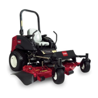
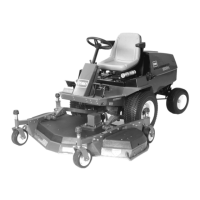
Product Overview
Figure 6
1. Motion control lever 5. Mower deck lift lever
2. Seat
6. Fuel cap (both sides)
3. Seat belt 7. Roll bar
4. Parking brake lever
Figure 7
1. Ignition switch 5. Oil pressure warning light
2. Engine coolant
temperature warning
light
6. Charge indicator light
3. Glow plug light 7. Throttle lever
4. Power take off (PTO) Switch
8. Hour meter
Controls
Become familiar with all the controls before y ou
star t the engine and operate the mac hine ( Figure 6
and Figure 7 ).
Motion Control Levers
T he motion control lev ers control the forw ard
and rearw ard motions as w ell as the tur ning of the
mac hine . R efer to Dri ving F orw ard or Bac kw ard
in Operation , pag e 25 .
Parking Brake Lever
W henev er the engine is shut off , eng ag e the
parking brak e to prev ent accidental mo v ement of
the mac hine . T o eng ag e the parking brak e , pull the
parking brak e lev er rearw ard and up ( Figure 8 ). T o
release the parking brak e , push the parking brak e
lev er forw ard and do wn.
Figure 8
1. Parking brake lever 2. Mower deck lift lever
Do not par k the traction unit on a slope.
Deck Lift Lever
T he dec k lift lev er acti v ates the h y draulic circuit
that raises and lo w ers the mo w er dec k. Pull bac k
on the lev er to raise the mo w er dec k and push
forw ard on it to lo w er it.
Important: Do not contin ue to hold the
lev er back or f orw ard after the mo w er deck
has been full y raised or lo w er ed. Doing so will
dama ge the h y draulic system.
Ignition Switch
T he ignition switc h has three positions: Off ,
On/Preheat, and Star t.
22

 Loading...


