1. OUTLINE EO10-33016A
1.5 Electronics Specifications
1-10
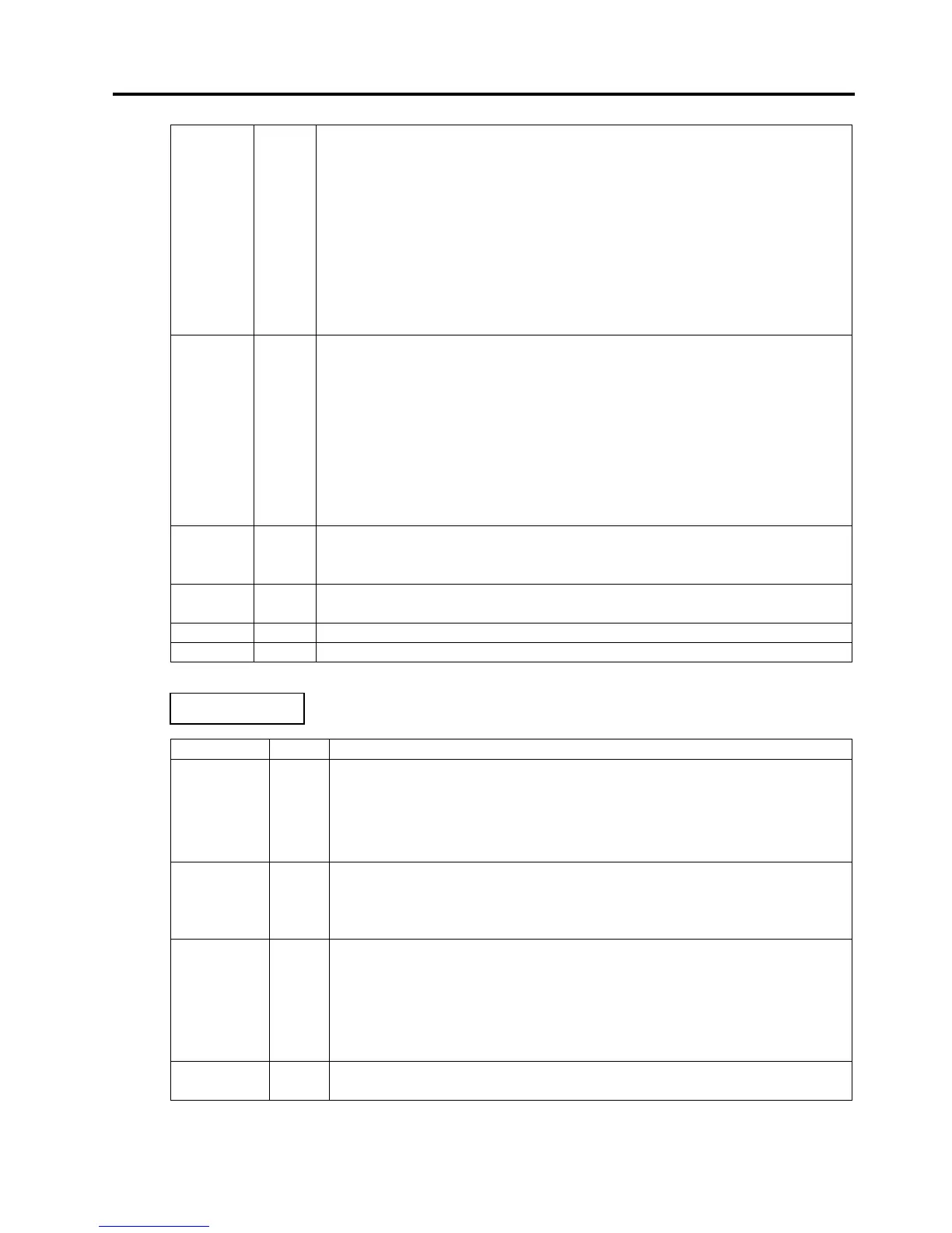
Select Output
This is an output signal which indicates whether the printer is in Pause state
or placed online. The printer can receive data while placed online.
z The signal is at “Low” level while the printer is in a Pause state.
z
The signal is kept at “Low” level (in a Pause state) until one of the following
states is cleared.
• Pause state caused by the [PAUSE] key
• Paper end state
• Ribbon end state
• Head open state
• Printer error state
• Initialization in progress upon power on or receipt of the nInit signal
nFault Output
z Output signal indicating that the printer is in a Fault state.
z At “Low” level while the printer is in a Fault state.
z The signal is kept at “Low” level (in a Fault state) until one of the followi
states is cleared.
• Pause state caused by the [PAUSE] key
• Paper end state
• Ribbon end state
• Head open state
• Printer error state
• Initialization in progress upon power on or receipt of the nInit signal
Perror Output
z Output signal indicating a label end or ribbon end state.
z At “High” level when the printer is in a label end or ribbon end state.
z Turns to “Low” level when the label end or ribbon end state is cleared.
+5V ---- z This is not a signal but a +5 V power supply voltage.
z The maximum current of 500 mA can be taken out.
nSelectIn
Input Not used
nAutoFd Input Not used
Signal I/O Description
PtrClk Output
z Reverse data transfer phase:
It is used for evaluating data sent to the
host.
z Reverse idle phase: When the printer changes the signal from
Low to High, an interrupt informing the host
that the data is available, occurs
PtrBusy Output
z Reverse data transfer phase:
Data bit 3 is used for the first transfer. Data
bit 7 is used for the second transfer.
the forward channel is in a Busy
z Reverse data transfer phase:
Data bit 2 is used for the first transfer. Data
bit 6 is used for the second transfer.
z Reverse idle phase:
This signal is set to high until the data
requested by the host. Then, the
process is performed according to the
nDataAvail signal.
Xflag Input z Reverse data transfer phase:
Data bit 1 is used for the first transfer. Data
bit 5 is used for the second transfer.
 Loading...