EasyManuals Logo

Toshiba B-SA4T Series Product Description

Toshiba B-SA4T Series
45 pages
To Next Page IconTo Next Page
To Previous Page IconTo Previous Page
Page #21 background imageLoading...
Page #21 background image
1. OUTLINE EO10-33016A
1.5 Electronics Specifications
1-19
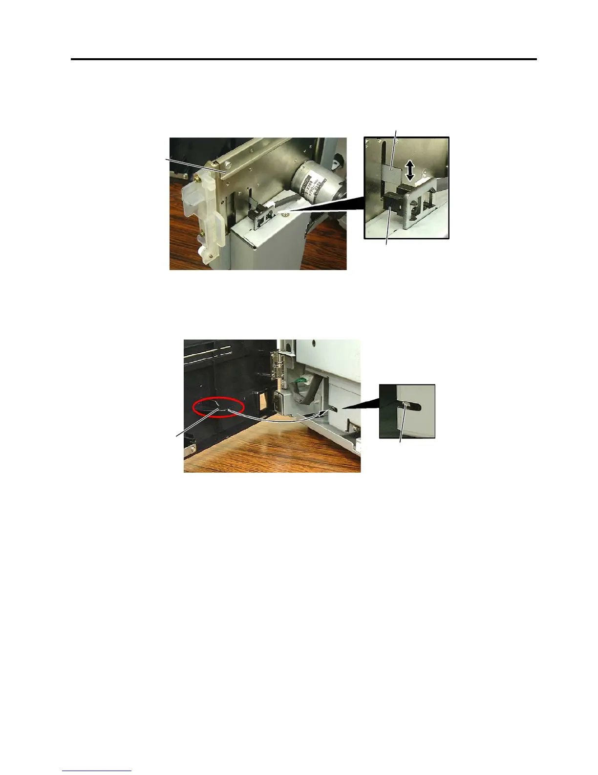
(6) Cutter home position sensor for optional cutter module
This sensor is positioned inside of the cutter unit. This is a photo-coupler, consisting of an LED
and a transistor. When the arm linked with the cutter blade intercepts the photo-coupler, it is
considered as a cutter home position.
(7) Cutter front cover sensor (micro switch)
The cutter front cover sensor is a micro switch, which is provided on the lower left of the cutter
unit. When the cutter front cover is closed, the arm of the cover turns the micro switch. A cutter
front cover status is detected depending on the micro switch is turned on or off.
Cutter Home
Position Sensor
Cutter Front Cover Sensor
Arm
Cutter Unit
Arm

Other manuals for Toshiba B-SA4T Series

Questions and Answers:

Question and Answer IconNeed help?

Do you have a question about the Toshiba B-SA4T Series and is the answer not in the manual?

Toshiba B-SA4T Series Specifications

General IconGeneral
Print TechnologyThermal Transfer / Direct Thermal
Print SpeedUp to 152.4 mm/sec (6 ips)
Max Print Width104 mm (4.09")
Resolution300 dpi
ConnectivityUSB 2.0
Optional InterfacesWireless LAN
BarcodesUPC/EAN/JAN, Code 39, Code 93, Code 128, EAN 128, NW7, Industrial 2 of 5, Postnet, RM4SCC, KIX-Code
2D CodesData Matrix, PDF417, QR Code, Maxi Code, Micro PDF417, Aztec Code
Media Thickness0.06 – 0.19 mm
Media Roll DiameterMax. 127 mm
Ribbon LengthUp to 300 m
Weight15 kg

Related product manuals