41
A
C
Wiring diagrams
Indoor units
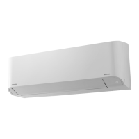
Low wall
MM-S056, MM-SR056, MM-S080, MM-SR080
7
Symbol Part name
F Fuse (PCB)
FM Fan motor
PMV Pulse modulating valve
PS Pressure sensor
RC Running capacitor
RY01-RY04 Relay
TA Temperature sensor
TC1 Temperature sensor
TC2 Temperature sensor
TR Transformer
1. The dashed line indicates wiring on the site.
2. indicates terminal blocks and the numbers
within them are terminal numbers.
Remote
controller
(Optional)
Infrared
receiver
(IR model)
Power supply
220/240 V – 50 Hz
Communication
 Loading...