40
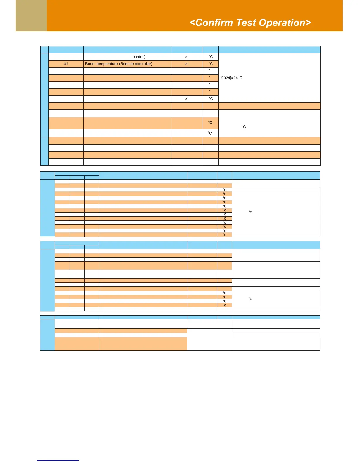
Monitor Function
.oNEDOC
Indoor unit data *
2
00 Room temperature (Use to
C1×Indoor suction air temperature (TA)20
C
1×)JCT(erutarepmetliocroodnI30
C
1×
1×
)2CT(erutarepmetliocroodnI40
C
1×)1CT(erutarepmetliocroodnI50
06 Indoor discharge air temperature (TF)
*
1
slp0051=]0510[slp01/1×gninepoVMPr
h
odnI
Filter sign time
80
System data
stinu84=]8400[tinu1×stinuroodnidetcennocfo.oNA0
0B Total horsepower of connected indoor units ×10 HP [
[2500} = 2500h
0415]=41.5HP
[0003]=3 unitstinu1×stinuroodtuodetcennocfo.oNC0
PH24=]0240[PH01×stinuroodtuoforewopesrohlatoTD0
F9
Suction temperature of air to air heat
exchanger (TSA)
*1
×1
[0024] = 24
F
F3
A
Outside air temperature (TOA)
*1
×1
U1 U2 U3
10 20 30 MPa
11 21 31 MPa
12 22 32
13 23 33
15 25 35
16 26 36
17 27 37
18 28 38
19 29 39
1A 2A 3A
1C 2C 3C
1D 2D 3D
1E 2E 3E
1F 2F 3F
U1 U2 U3
50 60 70 pls
51 61 71 pls
52 62 72 pls
53
63 73 A
54
64 74 A
56 66 76 rps
57 67 77 rps
59 69 79 mode
5A 6A 7A
5B 6B 7B
5D 6D 7D
5E 6E 7E
5F 6F 7F HP
Outdoor unit
individual data 3
*5
90 Heating/cooling recovery controlled
0: Normal
1: Recovery controlled
[0010]=Heating recovery controlled
[0001]=Cooling recovery controlled
91 Pressure release
0: Normal
1: Release controll ed
[0010]=Pressure release controlled
92
Data name Display format
Unit
Remote controller display example
Data name Display format
Unit
Remote controller display example
Data name Display format
Unit
Remote contr
oller display example
Data name Display format
Unit
Remote controller display example
.oNEDOC
dellortnocesaelererutarepmetegrahcsiD=]1000[esaelererutarepmetegrahcsiD
93
Follower unit release
(U2/U3 outdoor units)
[0100]=U2 outdoor unit release controlled
[0010]=U3 outdoor unit release controlled
[0001]=U4 outdoor unit release controlled
1×erutarepmetknistaeh2UDPIrosserpmoC
1×erutarepmetknistaeh1UDPInafroodtuO
1×erutarepmetknist
aeh2UDPInafroodtuO
PH61=]6100[1×rewopesrohtinuroodtuO
[0135] = 13.5A
1 fan model : Compressor 2 and Outdoor fan 1 current (I2)
2 fan model : Compressor 2 and Outdoor fan 2 current (I2)
×10
01×snoitulover1rosserpmoC
[0642] = 64.2rps
01×snoitulover2rosserpmoC
Outdoor unit individual data 2
*4
1×gninepo1VMP
[0500] = 500pls1×gninepo3VMP
1×gninepo4VMP
1 fan model : Compressor 1 curent (I1)
2 fan model : Compressor 1 and Outdoor fan 1 current (I1)
×10
edom85=]8500[1×ed
omnafroodtuO
1×erutarepmetknistaeh1UDPIrosserpmoC
[0024] = 24
CODE No.
1×)1LT(edisdiuqiltaerutarepmeT
1×)2LT(edisdiuqiltaerutarepmeT
1×)3LT(edisdiuqiltaerutarepmeT
Outdoor unit individual data 1
*3
001×)dP(erusserpnoitnetedrosneserusserp-hgiH
[0123] = 1.23MPa
001×)sP(erusserpnoitnetedrosneserusserp-woL
1×)1DT(erutarepmetegrahcsid1rosserpmoC
×1
1×)OT(erutarepmettneibmaedistuO
1×)1ST(erutarepmetnoitcuS
1×)3ST(erutarepmetnoitcuS
[0024] = 24
1×)2DT(erutarepmetegrahcsid2rosserpmoC
1×)1ET(erutarepmetliocroodtuO
1×)2ET(erutarepmetliocroodtuO
1×)1GT(erutarepmetliocroodtuO
Outdoor coil temperature (TG2)
CODE No.
*1 Only a part of indoor unit types is installed with the discharge air temperature sensor. This temperature is not
displayed for other types.
*2 When the units are connected to a group, data of the header indoor unit only can be displayed.
*3 The first digit of an CODE No. indicates the outdoor unit number.
*4 The upper digit of an CODE No. -4 indicates the outdoor unit number.
1 , 5 ... U1 outdoor unit (Header unit)
2
*
, 6 ... U2 outdoor unit (Follower unit 1)
3 , 7 ... U3 outdoor unit (Follower unit 2)
*5 Only the CODE No. 9* of U1 outdoor unit (Header unit) is displayed.
*
*
*
*
*