E6581697
F-116
6
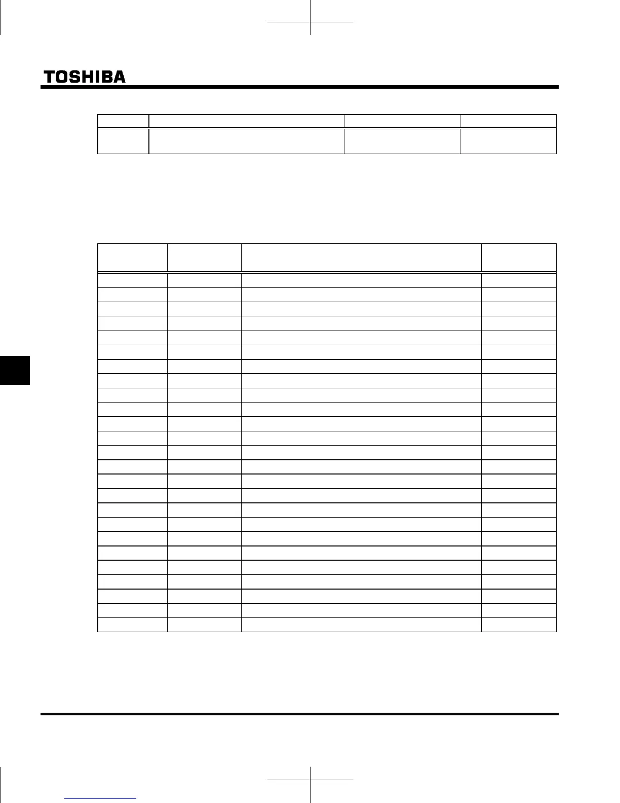
Ex.) When using the S3 terminal as the tracing back trigger signal terminal
Title Function Adjustment range Example of setting
f116 Input terminal function selection 6 (S3) 0-203
76: TRACE (Trace
back trigger signal)
Setting value 77 is reverse signal.
Note 1: If the inverter trips when no trigger signal is given, trace data is overwritten with tripping data.
Note 2: Trace data is overwritten each time a trigger signal is given.
Note 3: When retry operation is occurred, the data at first tripping is written. The trace data is cleared at retry success.
[Setup values of
f742 to f745]
Default setting
Communication
No.
Trace (monitor) function
Communication
unit at tracing
0
FD00 Operation frequency 0.01Hz
1
FD03 Output current 0.01%
2
FD02 Frequency setting value 0.01Hz
3
FD04 Input voltage (DC detection) 0.01%
4
FD05 Output voltage (command value) 0.01%
5
FD29 Input power 0.01kW
6
FD30 Output power 0.01kW
7
FD18 Torque 0.01%
9
FD23 Motor cumulative load factor 0.01%
10
FD24 Inverter cumulative load factor 0.01%
11
FD25 PBR (Braking resistor) cumulative load factor 0.01%
12
FD15 Frequency setting value (after compensation) 0.01Hz
13
FE35 VIA input value 0.01%
14
FE36 VIB input value 0.01%
18
FA51 Arbitrary code from communication -
20
FE37 VIC input value 0.01%
21
FE56 Pulse train input value 1pps
23
FD22 PID feedback value 0.01Hz
24
FE76 Input power 1kWh
25
FE77 Output power 1kWh
26
FE26 Motor load factor 1%
27
FE27 Drive load factor 1%
40
FD06 Input terminal status -
41
FD07 Output terminal status -
42
FD01 Inverter status -
■ Acquisition of trace data
Trace data is acquired through a communication device.
 Loading...


