E6581697
G-11
7
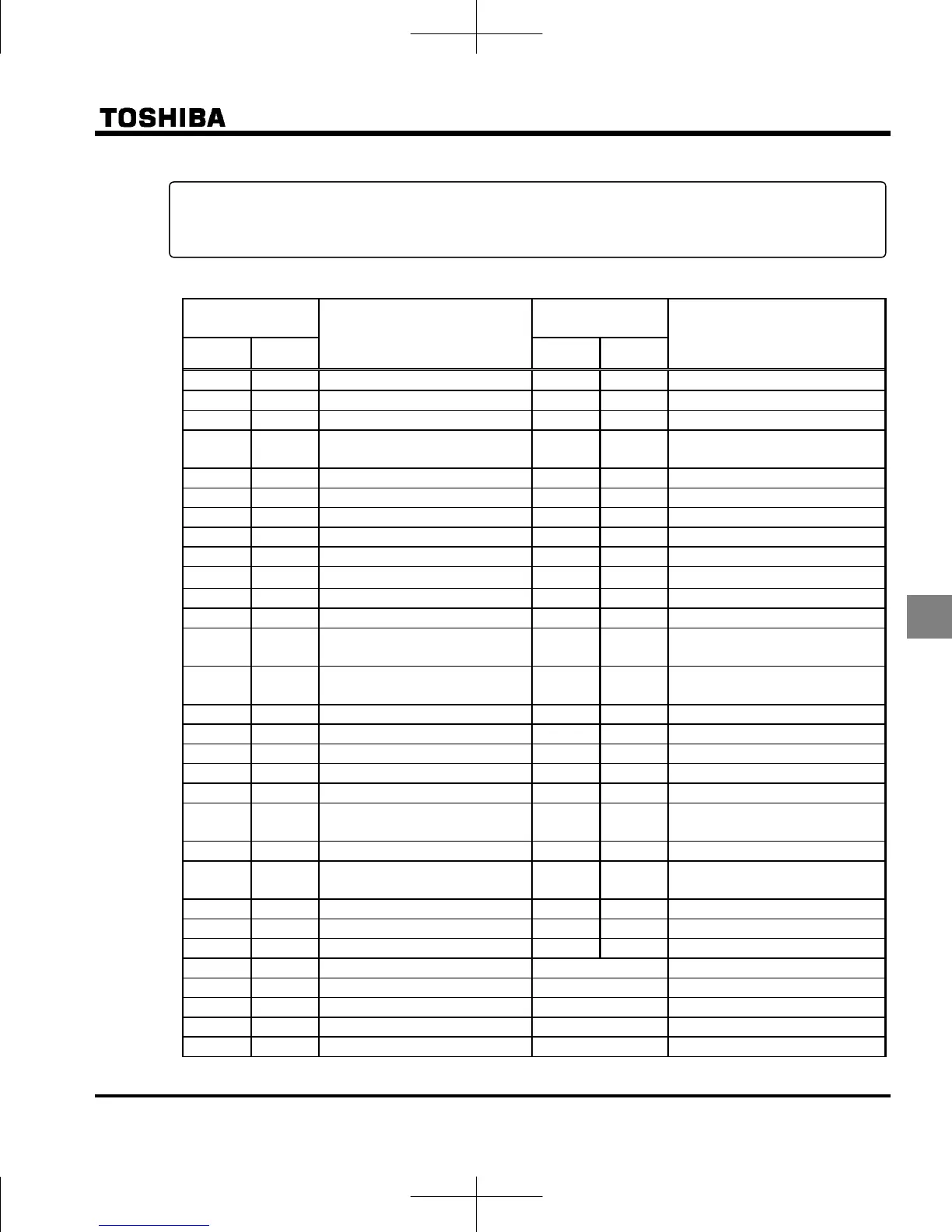
List of output terminal function settings
List of detection levels for output terminal selection
Parameter
programmed value
Parameter
programmed value
Positive
logic
Negative
logic
Function
Positive
logic
Negative
logic
Function
Frequency lower limit Light load output
Frequency upper limit Heavy load output
Low-speed detection signal Lower limit frequency stop
Output frequency attainment signal
(acceleration/deceleration completed)
Power failure synchronized operation
Set frequency attainment signal Traverse in progress
Fault signal (trip output) Traverse deceleration in progress
Over-current pre-alarm Parts replacement alarm
Overload pre-alarm Over-torque detection pre-alarm
Overheat pre-alarm Frequency setting mode selection 1/2
Overvoltage pre-alarm Panel / remote selection
Power circuit undervoltage detection Forced continuous operation in progress
Small current detection Specified frequency operation in progress
Over-torque detection Signal in accordance of frequency
command
Braking resistor overload pre-alarm Fault signal (output also at a retry
waiting)
Run/Stop PTC input alarm signal
Heavy fault Safe torque off signal
Light fault Analog input break detection alarm
Cooling fan ON/OFF F terminal state
In jogging operation R terminal status
Operation panel / terminal board
operation
Cooling fan replacement alarm
Cumulative operation time alarm Number of starting alarm
Communication option
communication error
Acceleration operation in progress
Forward/reverse run Deceleration operation in progress
Ready for operation 1 Constant speed operation in progress
Ready for operation 2 DC braking in progress
Brake release to Factory specific coefficient *1
Pre-alarm to Logic sequence function output 1 to 16
RS485 communication error Always OFF
Designated data output 1 Always ON
Designated data output 2
*1: Factory specific coefficients are manufacturer setting menus. Do not change the value of these parameters.
<Explanation of terminology>
Alarm …... Alarm output when a setting has been exceeded.
Pre-alarm …... Alarm output when the inverter may cause a trip during continued operation.
 Loading...


