E6581697
H-7
8
(Continued)
Item displayed
Panel
operated
LED
display
Communic
ation No.
Description
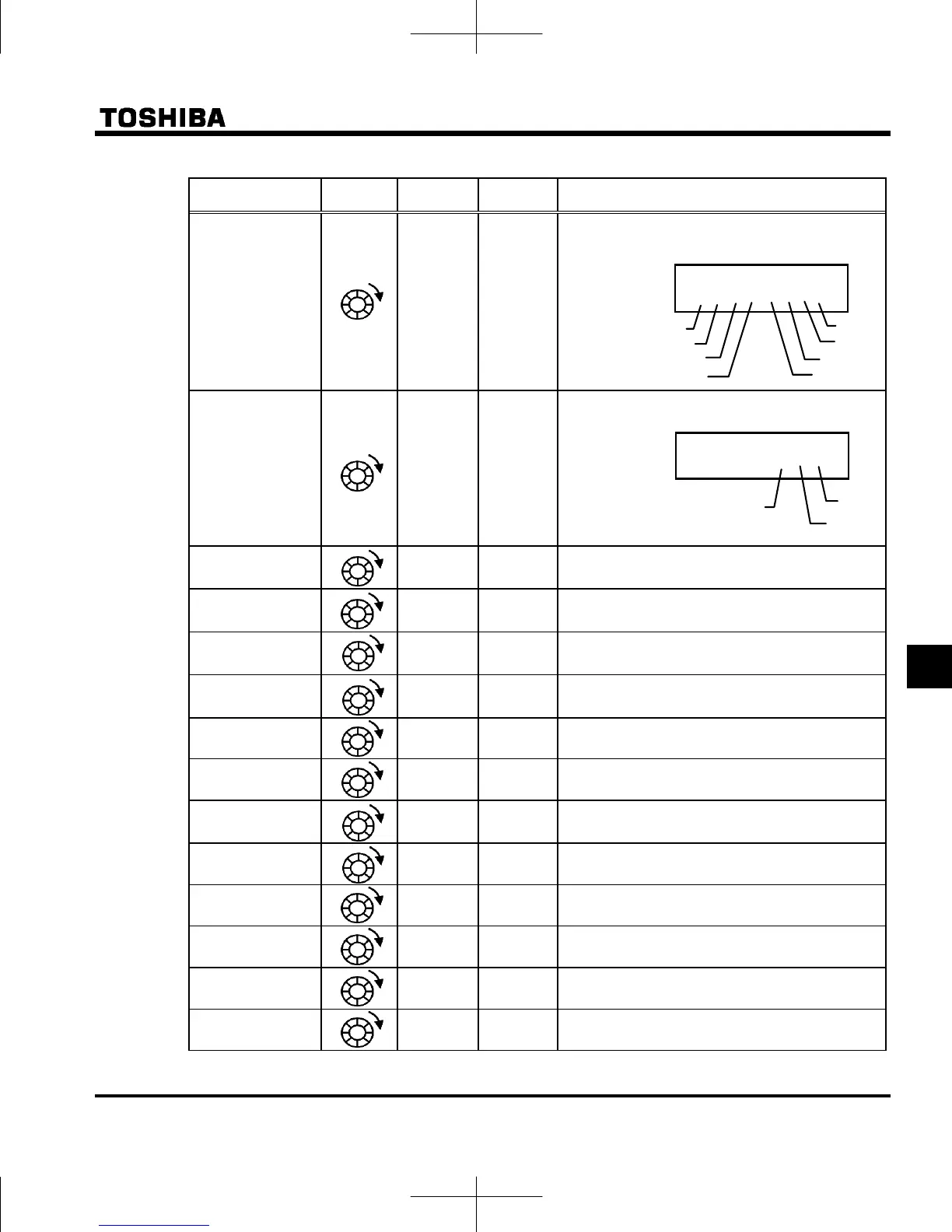
Input terminal
}}i}}i}i
FE06
The ON/OFF status of each of the control signal
input terminals (F, R, RES, S1, S2, S3, VIB, VIA)
are displayed in bits.
ON:
OFF:
Output terminal
0 }ii FE07
The ON/OFF status of each of the control signal
output terminals (RY-RC, OUT, FL) are displayed
in bits.
ON:
OFF:
CPU1 version
FE08 The version of the CPU1 is displayed.
CPU2 version
FE73 The version of the CPU2 is displayed.
Inverter rated
current
FE70 The inverter rated current (A) is displayed.
Overload and
region setting
0998
0099
The inverter overload characteristic and region
setting is displayed.
Past trip 1
FE10 Past trip 1 (displayed alternately)
Past trip 2
FE11 Past trip 2 (displayed alternately)
Past trip 3
FE12 Past trip 3 (displayed alternately)
Past trip 4
FE13 Past trip 4 (displayed alternately)
Past trip 5
FD10 Past trip 5 (displayed alternately)
Past trip 6
FD11 Past trip 6 (displayed alternately)
Past trip 7
FD12 Past trip 7 (displayed alternately)
Past trip 8
FD13 Past trip 8 (displayed alternately)
Refer to page H-8 for notes. (Continued overleaf)
Note 4
}}i}}i}i
VIA
S3
F
R
S2
VIB
S1
RES
Note 7
Note 7
Note 7
Note 7
Note 5
0 }ii
FL
RY-RC
OUT
Note 7
Note 7
Note 7
Note 7
Note 6
 Loading...


