E6581697
H-8
8
MODE
(Continued)
Item displayed
Panel
operated
LED
display
Communic
ation No.
Description
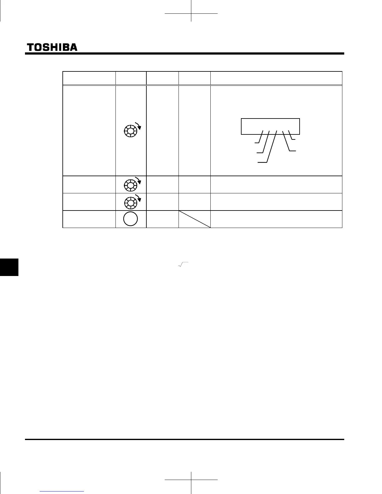
Parts replacement
alarm information
m }}}}i
FE79
The ON/OFF status of each of the cooling fan,
circuit board capacitor, main circuit capacitor of
parts replacement alarm, cumulative operation
time or number of starting are displayed in bits.
ON:
OFF:
Cumulative
operation time
FE14
The cumulative operation time is displayed.
(0.1=10 hours, 1.00=100 hours)
Number of starting
FD32 Number of starting (10000 times)
Default display
mode
The cause of the trip is displayed.
Note 1: The characters to the left disappear 100 Hz or more. (Ex: 120 Hz is )
Note 2: You can switch between % and A (ampere)/V (volt), using the parameter (current/voltage unit
selection).
Note 3: The input (DC) voltage displayed is 1/
2
times as large as the rectified d.c. input voltage.
Note 4: < VIA bar > = 3, 4 (Contact input): activated ON/OFF depend on VIA terminal input.
= 0 to 2 (Analog input): always OFF.
< VIB bar >
=1 to 4 (Contact input): activated ON/OFF depend on VIB terminal input.
= 0 (Analog input): always OFF.
< S3 bar >
47 = 0 (Contact input): activated ON/OFF depend on S3 terminal input.
47 =1 (PTC input): always OFF.
< S2 bar >
46 = 0 (Contact input): activated ON/OFF depend on S2 terminal input.
46 =1 (Pulse train input): always OFF.
Note 5: < OUT bar >
= 0 (Logic output): activated ON/OFF depend on OUT terminal output.
=1 (Pulse train output): always OFF.
Note 6: Overload characteristic of inverter and region setting are displayed as following monitor.
c-xx : aul=1 (Constant torque characteristic) is selected.
v-xx : aul=2 (Variable torque characteristic) is selected.
x-eu : Setup menu is selected to eu.
x-
as : Setup menu is selected to asia.
x-us : Setup menu is selected to usa.
x-jp : Setup menu is selected to jp.
Note 9
Note 8
}}}}i
Cooling fan
Cumulative
operation time
Control circuit board
capacitor
Main circuit
capacitor
Number of starting
 Loading...


