E6581697
H-9
8
Note 7: Past trip records are displayed in the following sequence: 1 (latest trip record) 2345678
(oldest trip record). If no trip occurred in the past, the message “
” will be displayed. Details on
past trip record 1 to 8 can be displayed by pressing the center of the setting dial when past trip 1 to 8 is
displayed. Refer to section 8.2.2 for details.
Note 8: Parts replacement alarm is displayed based on the value calculated from the annual average ambient
temperature specified using
, the ON time of the inverter, the operating time of the motor and the
output current ( load factor). Use this alarm as a guide only, since it is based on a rough estimation.
Note 9: The cumulative operation time increments only when the machine is in operation.
Note 10: If there is no trip record,
nerr is displayed.
Note 11: Of the items displayed on the monitor, the reference values of items expressed in percent are listed below.
Output current: The current monitored is displayed. The unit can be switched to A (amperes).
Input voltage: The voltage displayed is the voltage determined by converting the voltage
measured in the DC section into an AC voltage. The reference value (100%
value) is 200V (240V class), 400V (500V class). The unit can be switched to V
(volts).
Output voltage: The voltage displayed is the output command voltage. 100% reference value
is 200V. This unit can be switched to V (volts).
Load factor of inverter: Depending on the PWM carrier frequency (f300) setting and so on, the
actual rated current may become smaller than the rated output current
indicated on the nameplate. With the actual rated current at that time (after a
reduction) as 100%, the proportion of the load current to the rated current is
indicated in percent. The load factor is also used to calculate the conditions
for overload trip (
).
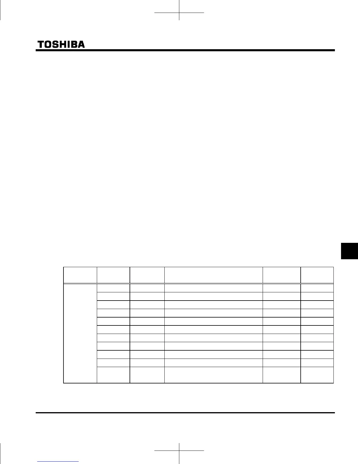
Note 12: Status monitor of * mark is displayed by
to and setting.
The left side character is as following table by each parameter setting number.
Parameter Setting No. LED display Function Unit
Communic
ation No.
0
x60.0
Output frequency Hz / free unit FE00
1
c16.5
Output current *1 % / A FC02
2
f50.0
Frequency command value Hz / free unit FE02
3
y100
Input voltage (DC detection) *1 % / V FC05
4
p 90
Output voltage (command value) *1 % / V FC08
5
k 3.0
Input power kW FC06
6
h 2.8
Output power kW FC07
7
q 80
Torque *1 % FC04
9
g 60
Motor cumulative load factor % FE23
10
l 80
Inverter cumulative load factor % FE24
to
,
11
r 80
PBR (Braking resistor) cumulative load
factor
% FE25
 Loading...


