Do you have a question about the Toshiba TOSVERT VF-PS1 and is the answer not in the manual?
Explains the warning and caution markings used in the manual and on the inverter.
Details the meaning of various symbols used to indicate prohibitions, mandatory actions, warnings, and cautions.
Defines the intended use of the inverter and applications where it should not be used.
Provides critical safety guidelines for using the inverter, including application limitations and protective measures.
Instructions to verify the purchased product is correct and undamaged before use.
Explanation of the structure and meaning of the product code written on the label.
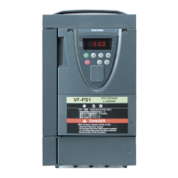
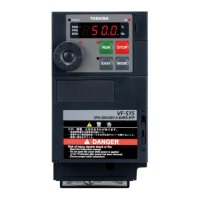
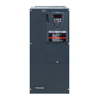
Illustrates and names the key external parts and components of the inverter unit.
Important considerations when using the inverter with motors, including comparisons with commercial power.
Detailed safety warnings and mandatory actions related to wiring the inverter.
Provides standard wiring diagrams for main circuit connections and safety precautions.
Details the functions and connections for main circuit and control circuit terminals.
Explains the three operating modes: standard, setting, and status monitor modes.
Describes basic operations like start/stop and frequency setting using terminal board or operation panel.
Explains how to set parameters in Quick mode and Standard setting mode, including adjustment ranges.
Details functions for searching parameters, viewing change history, and resetting parameters to defaults.
Allows searching for and viewing recently changed parameters, useful for repeated adjustments.
Covers manual and automatic settings for acceleration and deceleration times to match load conditions.
Explains parameters for automatic torque boost and auto-tuning to improve motor starting torque.
Describes how to configure automatic function settings for operation modes and frequency sources.
Details how to select the command mode (terminal, panel, communication) and frequency setting mode.
Explains how to select V/f control modes, including constant torque, torque boost, and sensorless vector control.
Covers manual adjustment of torque boost to increase torque at low speeds, especially for conveyors.
Sets the base frequency and voltage, which are crucial for defining the constant torque control area.
Determines the maximum output frequency, limited by motor ratings and cable length.
Sets the minimum and maximum output frequencies to define the operational range of the motor.
Adjusts how the inverter responds to analog signals for frequency commands.
Configures up to 15 preset speeds that can be selected via external contact signals.
Programs the motor direction control via RUN/STOP keys on the operation panel.
Configures electronic thermal protection levels and characteristics to protect the motor from overheating.
Allows switching the monitor display unit from percentage to amperes (A) or volts (V).
Covers configuration and calibration for analog output signals to meters.
Adjusts the PWM carrier frequency to control acoustic noise and electromagnetic noise.
Features like auto-restart and regenerative power ride-through for maintaining operation during power issues.
Settings for dynamic braking to achieve abrupt motor stops, including resistance and capacity.
Allows setting inverter parameters to factory defaults or specific configurations like 50Hz or 60Hz.
Explains functions for finding programmed parameters and resetting them to default values.
Details how to assign functions like quick mode switching and shortcut key operations to the EASY key.
Covers parameters for low-speed signal output and output terminal function selection.
Defines priority for simultaneous forward/reverse run commands and terminal input priority.
Allows assigning functions to input terminals, including always-on functions and modifying terminal functions.
Covers switching V/f characteristics and other basic parameter settings.
Allows arbitrary setting of V/f characteristics using up to five points for motor control.
Explains methods for switching between frequency command sources like terminals or operation panel.
Covers setting start/stop frequencies, run/stop control with signals, and frequency command dead zones.
Details parameters for DC braking, including start frequency, current, time, and priority control.
Covers auto-stop for continuous low-frequency operation and regenerative power ride-through.
Explains how to set up and operate the motor in jog mode using parameters and input terminals.
Configures up/down frequency setting using external contact signals for incremental adjustments.
Allows setting jump frequencies to avoid mechanical system resonance during operation.
Defines preset speed frequencies from 8 to 15 for stepped speed control.
Enables seamless switching between local and remote modes without affecting operation status.
Covers retry functions, regenerative power ride-through, and overvoltage/undervoltage protection.
Controls output frequency to prevent overvoltage trips during deceleration or constant speed operation.
Selects control mode behavior when an undervoltage condition is detected.
Sets the operation level for regenerative power ride-through control and deceleration stop.
Detects wire breakage on VI/II analog input and specifies actions upon detection.
Provides guidance on estimating the lifespan of components like cooling fans and capacitors.
Controls the activation time of the rush current suppression relay for direct current pass or multiple inverters.
Sets PTC thermal protection and monitors motor temperature to prevent overheating.
Details the overload time settings for braking resistors.
Configures restart conditions for motors stopped with a mechanical brake, ensuring safe operation.
Configures PTC thermal protection settings for motor overheating prevention.
Sets up failure monitoring for optional control power backup devices to ensure system reliability.
Sets the starting frequency for overload reduction to protect the motor at lower speeds.
Enables or disables input phase failure detection to prevent inverter damage under abnormal conditions.
Configures detection and tripping for low current conditions to protect the motor and inverter.
Enables detection of short circuits on the inverter's output side at startup for safety.
Sets parameters for overtorque detection during power running and regenerative braking.
Sets the cooling fan to operate only when required, extending its lifespan.
Allows setting an alarm for when the cumulative operation time reaches a specified limit.
Monitors motor speed and outputs an error signal if it deviates from specified limits.
Controls output frequency to prevent overvoltage trips during deceleration or constant speed operation.
Selects control mode behavior when an undervoltage condition is detected.
Sets the operation level for regenerative power ride-through control and deceleration stop.
Detects wire breakage on VI/II analog input and specifies actions upon detection.
Allows setting inverter parameters to factory defaults or specific configurations like 50Hz or 60Hz.
Explains functions for finding programmed parameters and resetting them to default values.
Details how to assign functions like quick mode switching and shortcut key operations to the EASY key.
Covers inverter control via external signals for operation, speed command, and mode selection.
Details functions of input terminals (sink logic) and output terminals.
Explains how to set up analog input terminals for frequency control using RR/S4 or VI/II terminals.
Describes the layout and elements displayed in the inverter's status monitor mode.
Explains how to monitor various inverter statuses like frequency, current, voltage, and terminal states.
Allows customization of displayed items in the status monitor mode using optional monitor functions.
Lists error codes and their descriptions, indicating possible causes and remedies for inverter trips.
Details the codes and panel indications for various alarms and pre-alarms monitored via communication.
Explains how to ensure inverter installation and wiring comply with EMC and low-voltage directives.
Provides cautions regarding installation, wiring, rated current, and peripheral devices for UL/CSA compliance.
Discusses the inverter's safety functions (power removal) and compliance with IEC/EN standards.
Lists recommended wire sizes, AIC ratings, fuse classes, and grounding wire sizes for various models.
Explains when and how to install magnetic contactors in primary and secondary circuits for safety and control.
Details when to install overload relays, especially for motors with different current ratings or output.
Describes optional devices like AC/DC reactors, EMC filters, braking resistors, and their functions.
Provides detailed specifications for various inverter models, including electrical and environmental data.
Presents dimensional drawings and weights for different inverter models and their configurations.
Lists common error codes, their possible causes, and recommended remedies for troubleshooting.
Explains procedures for resetting the inverter after a trip, including safety precautions.
Provides a troubleshooting guide for diagnosing motor operation issues when no trip message appears.
Lists common operational issues with their causes and remedies, such as incorrect motor direction.
Outlines routine checks for the inverter's installation environment and components.
Details periodic inspection items and procedures to maintain inverter performance and prevent failure.
Provides instructions on how to contact the service network for repairs and necessary information.
Offers precautions for storing the inverter temporarily or for extended periods to maintain its performance.
| Series | VF-PS1 |
|---|---|
| Cooling Method | Forced air cooling |
| Protection Class | IP20 |
| Horsepower Range | 0.5HP to 30HP |
| Rated Output Current | 2.5 to 90A |
| Control Method | V/f control |
| Overload Capacity | 150% for 60 seconds |
| Protection Functions | Overcurrent, Overvoltage, Undervoltage, Overheat, Short circuit |
| Protection Features | Stall prevention |
| Operating Temperature | -10°C to +50°C (14°F to 122°F) |
| Storage Temperature | -20°C (-4°F) |
| Humidity | 95% RH (non-condensing) |
| Altitude | 1000m (3280ft) or less |
| Vibration | 5.9 m/s² |
| Frequency | 50/60 Hz |