E6581386
B-10
2
2.3 Description of terminals
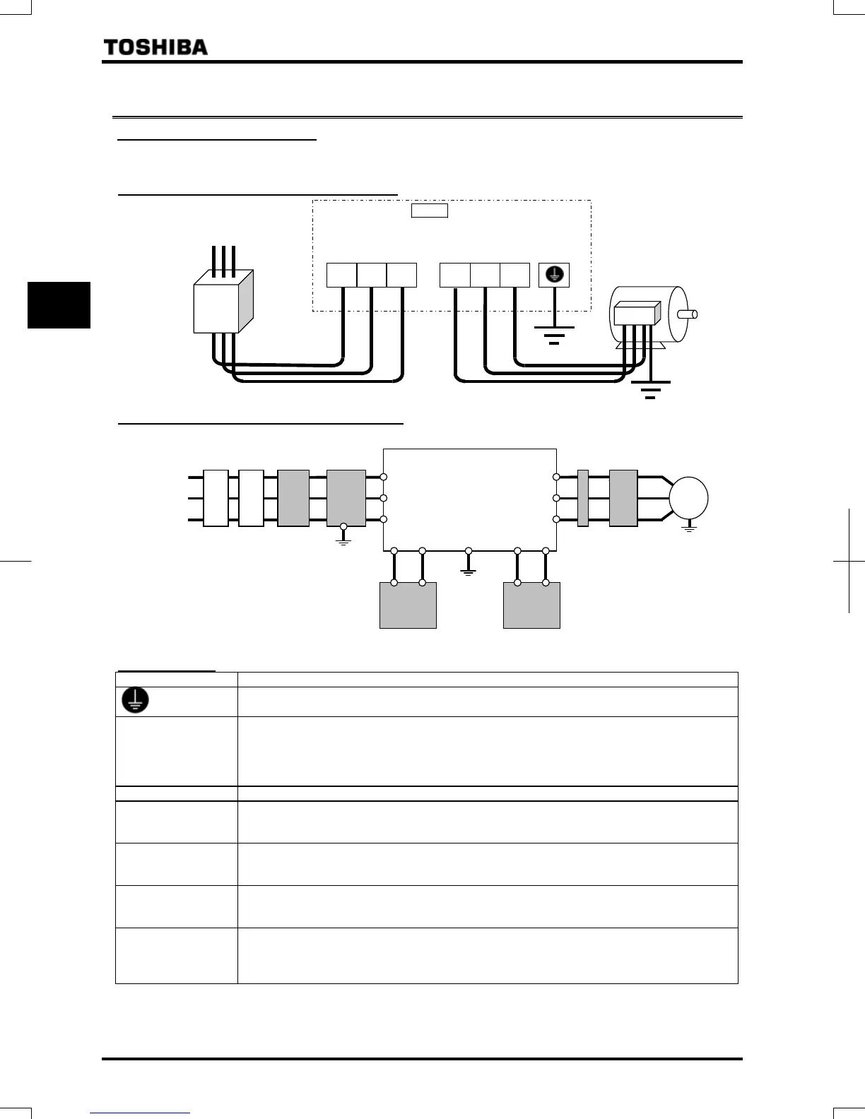
2.3.1 Main circuit terminals
This diagram shows an example of wiring of the main circuit. Use options if necessary.
Power supply and motor connections
Power supply
S/L2 T/L3
Motor
No-fuse
breaker
Connect the power
cables to RL1, S/L2,
and T/L3.
Connect the motor
cables to U/T1, V/T2
and W/T3.
VF-PS1
E
U/T1
V/T2 W/T3
R/L1
Connection with peripheral equipment
Motor
Zero-phase
reactor
Power
supply
Inverter
Braking resistor [Note]
Surge
suppressin
filter
DC reactor
EMC filter
Input AC
reactor
Magnetic
contactor
Molded-case
circuit breaker
R/L1
S/L2
T/L3
PA/+ P0
PA
PB
V/T2
U/T1
W/T3
IM
Note: Connect a braking unit
between the terminals PA/+
and PC/-, if necessary.
Main circuit
Terminal symbol Terminal function
Grounding terminal for inverter casing
R/L1, S/L2, T/L3
(R/L1.1, S/L2.1, T/L3.1,
R/L1.2, S/L2.2, T/L3.2)
*1
Power input terminal
200V class: 400V class:
0.4~90kW Three-phase 200~240V-50/60Hz 0.75~110kW Three-phase 380~480V-50/60Hz
132~630kW Three-phase 380~440V-50Hz
Three-phase 380~480V-60Hz
U/T1, V/T2, W/T3 Connect to a (3-phase induction) motor.
PA/+, PB
(PA, PB) *2
Connect a braking resistor.
Change the parameters , and if necessary.
250kW models and larger are not equipped with terminal PB.
PC/-
This is a negative potential terminal in the internal DC main circuit. DC power supply can be input
across the PA/+ terminals (positive potential). (For 200V-18.5kW and above models, and
400V-22kW and above models, an optional circuit is needed to suppress a rush current.)
PO, PA/+
Terminals for connecting a DC reactor (DCL: optional external device). Shorted by a short bar
when shipped from the factory (200V: 45kW or smaller, 400V: 75kW or smaller). Before installing
DCL, remove the short bar. (The rating of 400V-400kW~630 kW have the double terminals of PO.)
RO, SO, TO
200V class: 90kW 400V class:132kW~630kW
Inverter’s cooling fan power input terminals. When using a DC power supply, connect three-phase
power cables. When using DC power for the main circuit, be sure to connect a three-phase power
supply to these terminals. For more information, refer to Section 10.6.2
*1: Value in ( ) 400V-500, 630kW.
*2: Value in ( ) 200V-55kW or larger, 400V-90~220kW.
 Loading...