E6581386
E-5
5
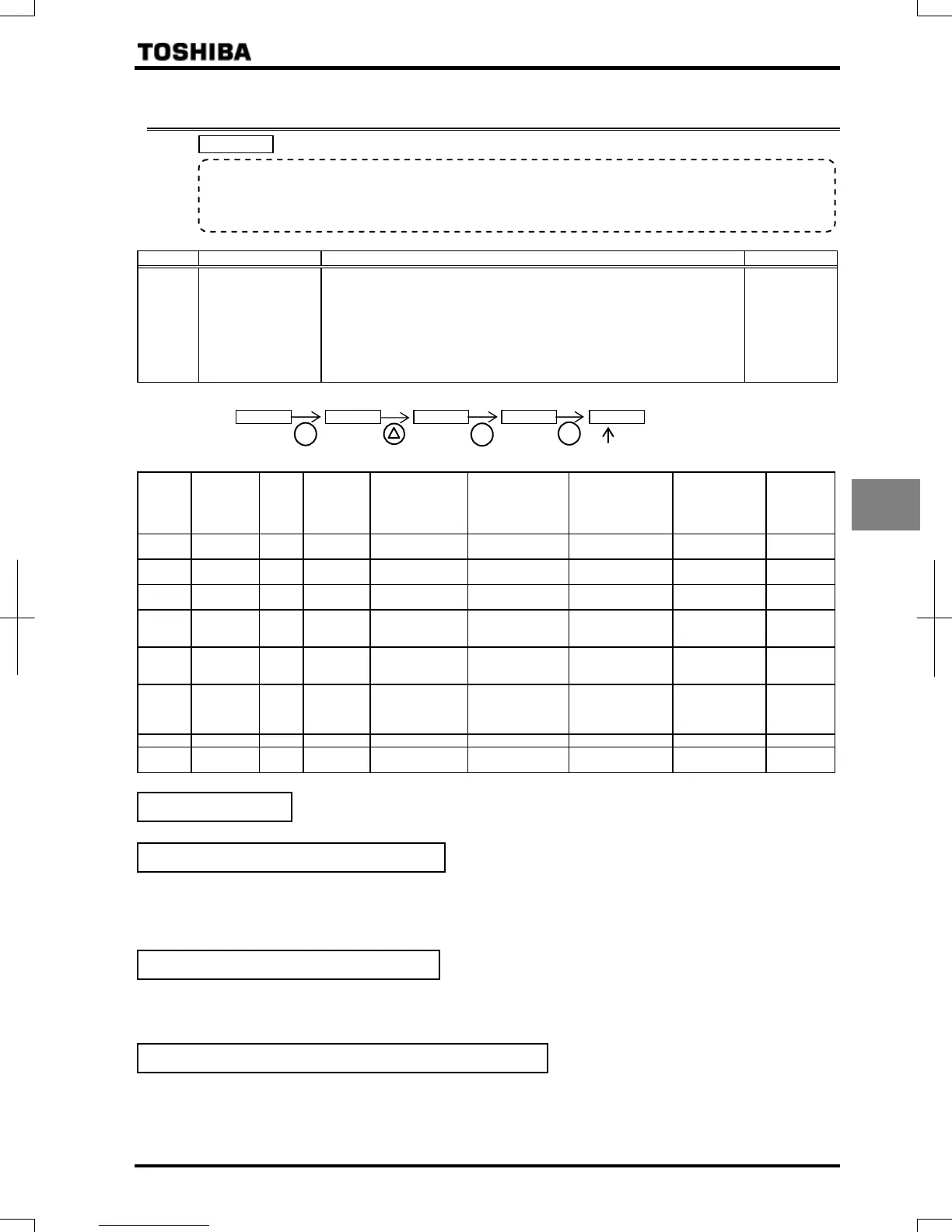
5.4 Setting parameters by operating method
: Automatic function setting
[Parameter setting]
Title Function Adjustment range Default setting
Automatic function
setting
:Disabled
:Frequency setting by means of voltage
:Frequency setting by means of current
:Voltage/current switching from external terminal
:Frequency setting on operation panel and operation by means of
terminal
:Frequency setting and operation on operation panel
:Coast stop
Example: When setting the parameter "=", It will be the following indication.
Automatically programmed functions and parameter set values
Default
setting
:
Disabled
:
Frequency
setting by
means of
voltage
:
Frequency
setting by
means of current
:
Voltage/current
switching from
external terminal
:
Frequency setting
on operation panel
and operation by
means of terminal
:
Frequency
setting and
operation on
operation panel
:
Coast stop
:Terminal
board
– – – –
:Terminal
board
:
Operation
panel
–
:RR/S4 –:RR/S4 :VI/II :RR/S4
:Operation
panel
:Operation
panel
–
:Voltage
input
– – :Current input :Current input – – –
:Standby – – – – – –
:No
function is
assigned
(S3)
:
Preset
speed
command 3
– – –
:Frequency
priority switching
– – :Standby
:/
terminal
switching
–
:/
terminal
switching
:/
terminal
switching
:/
terminal
switching
:/
terminal
switching
:/
terminal
switching
–
% – – % % – – –
:VI/II –:RR/S4 :VI/II :VI/II
:Operation
panel
:Operation
panel
–
Refer to Section 11 for input terminal functions.
No change is made to the parameter setting.
Operation is performed by applying a voltage for setting the RR/S4 terminal 1 frequency.
When sink logic is selected:
PWR-P24/PLC ON: Standby (ON (short-circuited) by default)
F-CC ON: Forward run
R-CC ON: Reverse run
This setting is used to set the frequency by applying a current of 4-20mA to the VI/II terminal.
PWR-P24/PLC ON: Standby (ON (short-circuited) by default)
F-CC ON: Forward run
R-CC ON: Reverse run
Switching between remote and local (different frequency commands) can be performed by turning on or off the S3 terminal.
In that case, apply a voltage via the RR/S4 terminal and a current via the VI/II terminal.
S3-CC OFF: The frequency is set according to the voltage applied to the RR/S4 terminal.
S3-CC ON: The frequency is set according to the current applied to the VI/II terminal.
In sink logic mode: PWR-P24/PLC ON: Standby (ON (short-circuited) by default), F-CC ON: Forward run, R-CC ON: Reverse run.
• Function
Automatically programs all parameters (parameters described below) related to the functions by
selecting the inverter's operating method.
The ma
or functions can be pro
rammed simpl
.
Disabled (
=
)
Frequency setting by means of voltage: (
=
)
Frequency setting by means of current
Voltage/current switching by means of an external terminal
ENT
3 times
A present set value is shown.
ENT
ENT
 Loading...