E6581386
E-34
5
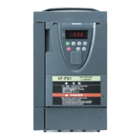
An example of setting when =
Motor speed
Time
In
ut volta
e
Deceleration stop
• Even after the recovery from an input power failure, the motor continues slowing down to a stop. If the voltage in the
inverter main circuit falls below a certain level, however, control will be stopped and the motor will coast.
• The deceleration time varies according to the setting of . In this case, the deceleration time refers to the
time elapsed before a motor running at (maximum frequency) comes to a full stop.
• If the voltage in main circuit below (Under voltage detection level ) at Non-stop control during power failure,
the motor will coast and inverter display is shown "(displayed alternately)". And then, If recovery from
the input power failure, the motor continues coasting.
5.19 Dynamic (regenerative) braking - For abrupt motor stop
: Dynamic braking selection
: Dynamic braking resistance
: Dynamic braking resistor capacity
: Braking resistance overload time
[Parameter setting]
Title Function Adjustment range Default setting
Setting Braking function ST-off
overload
detect
Disabled
-
―
protect
Enabled
not protect
protect
Enabled *1)
(It is effective
in trip.
condition.)
Disabled
not protect
protect
Enabled
not protect
protect
Dynamic braking selection
Enabled
(It isn't
effective in
trip.condition )
Disabled
not protect
Dynamic braking resistance ~ Ω
According to model
Refer to page K-42.
Dynamic braking resistor
capacity
~ kW
According to model
Refer to page K-42.
Braking resistance overload
time
~ sec.
*1) The state of olr trip is excluded.
* Default settings vary from model dependent. Refer to page E-38, 39.
Protection levels defined by (Refer to Section 6.15.2).
Note 1: The time set using is the time for which the resistor sustains an overload. (Enter the time elapsed
before the inverter trips if a load 10 times as large as the dynamic braking resistor capacity specified using
is applied.) There is no need to change resistance settings recommended by Toshiba (except DGP
resistance setting).
Note 2: If the parameter is set to - (Braking function enabled), the inverter will be set automatically so as to
deal with the regenerative energy from the motor by means of a resistor, without taking any action to limit
overcurrent. (The same function as =)
Note 3: For inverters with ratings of 400V-250kW and above, set to , because separate dynamic braking units
are not included as standard equipment.
• Function
Dynamic braking is used in the following cases:
1) Need to stop the motor quickly.
2) The inverter trips because of an overvoltage (OP) during deceleration.
3) Fluctuation of load condition causes a regenerative power even at a constant speed such as press machine.
 Loading...