E6581386
F-55
6
6.26.17 Guide to time of replacement
H : Annual average ambient temperature
• Function
You can set the inverter so that it will calculate the remaining useful life of the cooling fan, main circuit
capacitor and on-board capacitor from the ON time of the inverter, the operating time of the motor, the
output current (load factor) and the setting of
H
and that it will display and send out an alarm through
output terminals when each component is approaching the end of its useful life.
Title Function Adjustment range Default setting
H Annual average ambient temperature
: -10~+10°C
: +11~+20°C
: +21~+30°C
: +31~+40°C
: +41~+50°C
: +51~+60°C
Note 1: Using H, enter the annual average temperature around the inverter. Be careful not to enter the
annual highest temperature.
Note 2: Set H at the time of installation of the inverter, and do not change its setting after the start of use.
Changing the setting may cause a part replacement alarm calculation error.
6.26.18 Rush current suppression relay activation time
H : Rush current suppression relay activation time
• Function
This parameter is used to control the rush current suppressing resistor shorting relay when a direct current
is passed or multiple inverters are used with their DC sections connected to each other.
Title Function Adjustment range Default setting
H
Rush current suppression relay
activation time
~ sec.
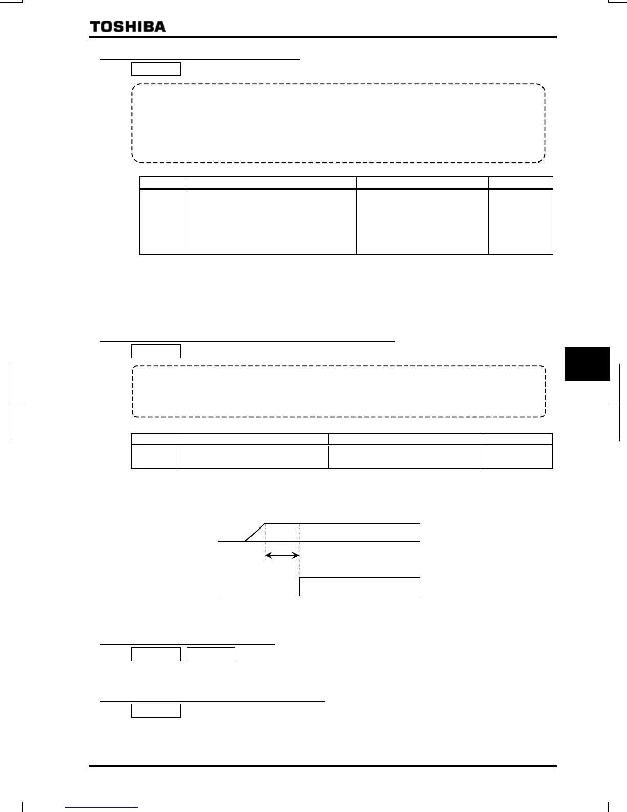
The rush current suppressing relay is activated on the expiration of the time limit set with parameter H after the
voltage in the DC section of the inverter has reached the specified level.
DC voltage
H
ON
Rush current
suppression relay
6.26.19 Motor thermal protection
H~ H : PTC thermal selection
⇒ For details, refer to Instruction Manual (E6581339) specified in Section 6.36.
6.26.20 Braking resistance overload curve
H : Braking resistance overload time
⇒ Refer to 5.19 for details.
 Loading...