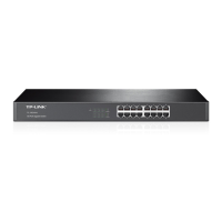
1. Check that the selected power supply is consistent with the power requirements marked on the switch;
2. Connect the original power cord of the switch to the switch and the power socket, as shown in the figure below.
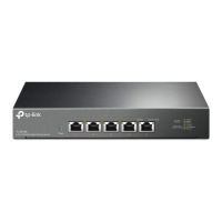
The Type-C Console port connection diagram is as follows.
3.4 Connect the power cord
Hardware connection
Figure 3-4Type-C Console port connection diagram
Layer 3 managed switch installation manual
Figure 3-5 Schematic diagram of power cord connection
13
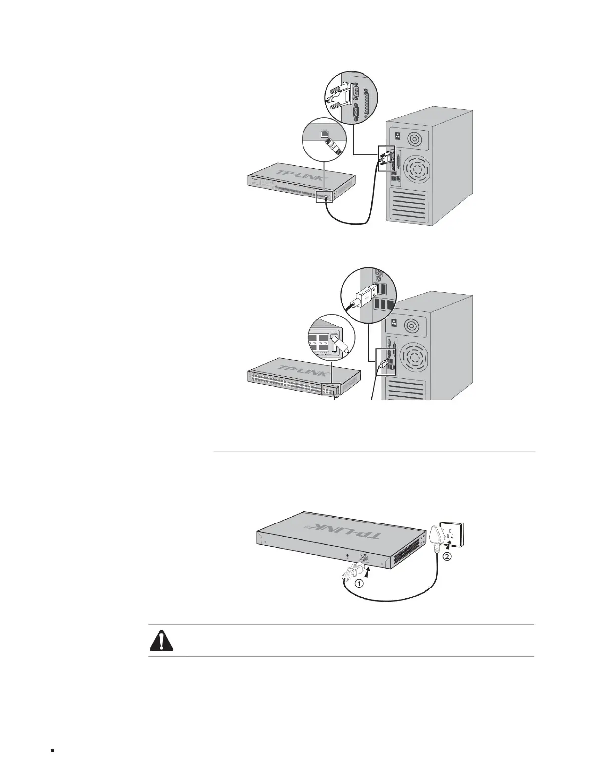
Figure 3-3RJ45 Console port connection diagram
Note: The power supply of the power supply system requires good contact with the earth. Confirm the position of the power supply switch of the equipment so that the
power supply can be cut off in time when necessary.
Machine Translated by Google