Chapter 3 Hardware Connection
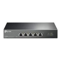
3.2 Connect the SFP+ port
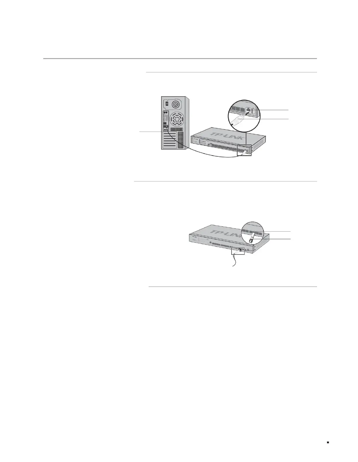
3.1 Connect the RJ45 port
3.3 Connect to the Console port
Optical module
RJ45 port
RJ45 port
SFP+ port
Hardware connection
Crystal Head
As shown in the figure below, connect the switch and the peer device through the RJ45 port.
As shown in the figure below, connect the SFP/SFP+ optical module or SFP+ cable to the SFP+ port. When using SFP+ cables, please ensure that the
minimum bending radius of the cable meets the requirements. The SFP+ port supports 10Gbps connection by default. If you use a Gigabit SFP
optical module, please set the SFP+ port rate to 1000Mbps first.
Connect to the Console port to log in to the switch. You can manage the switch through the command line. For specific login methods, please refer to
4.2 Local Login.
TL-ST5012F provides 1 Type-C Console port, and TL-ST5016F provides 1 Type-C Console port and 1 RJ45 Console port. The two ports cannot be
used at the same time. When connected at the same time, only the Type-C Console port takes effect.
The RJ45 Console port connection diagram is shown in Figure 3-3.
Layer 3 managed switch installation manual
Figure 3-1 RJ45 port connection diagram
Figure 3-2 SFP+ port connection diagram
12
Machine Translated by Google