INSTALLATION
Trace Engineering Co. Inc. Tel (360) 435-8826 Part Number 3179
5916 195
th
Street, NE Fax (360) 435-2229 Effective August 6, 1998
Arlington, WA 98223 USA www.traceengineering.com
Page
26
Cables must have crimped and/or soldered copper compression lugs unless aluminum mechanical
lugs are used. We suggest using high quality UL listed Trace Engineering battery cables. These
cables are available in a specific assortment of sizes from 1 ½ to 10 feet, and in 2/0 or 4/0 AWG.
They are color-coded and have pressure crimped, sealed ring terminals. Contact your Trace dealer
to order.
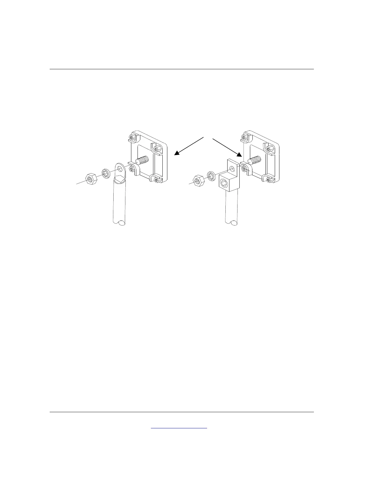
Figure 2, Battery to Inverter Cable Connection
.
Figure 2, Battery to Inverter Cable Connection illustrates proper connections for the Legend Series II
inverter/chargers. Points of caution are:
ü Do not connect the battery negative (-) terminal to the vehicle chassis; connect it to the
battery negative terminal of the inverter.
ü Do not connect the DC load negatives to the battery negative (-), connect only to the
chassis ground terminal on the inverter or to the vehicle chassis.
These connections are necessary in order for the RC7 remote control fuel gauge to work properly.
All current into or out of the battery must pass through the internal shunt, which is between the
chassis ground and battery negative terminals.
2/0 Copper Compression Lug
2/0 Aluminum Mechanical Lug
Do not place anything between
battery cable lug and terminal
surface. Assemble exactly as shown