THEORY OF INVERTER OPERATION
Trace Engineering Co. Inc. Tel (360) 435-8826 Part Number 3179
5916 195
th
Street, NE Fax (360) 435-2229 Effective August 6, 1998
Arlington, WA 98223 USA www.traceengineering.com
Page
56
Regulation
An advantage of a modified square wave compared to a square wave is the ability to regulate Root
Mean Square (RMS) voltage by means of varying the pulse width, and off time periods. The pulse
width variation method of regulation is referred to as pulse width modulation or PWM.
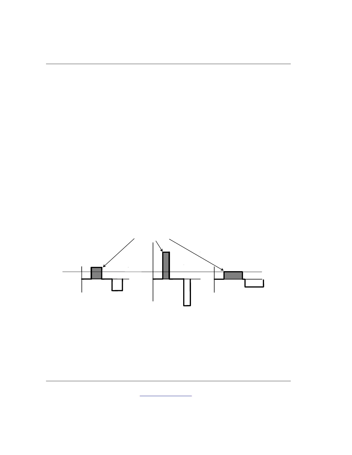
RMS regulation should keep the area inside the waveform equal at all times. Since the peak voltage,
or pulse height, is a product of battery voltage and transformer ratio, when the peak voltage
increases (Figure 12), the area inside the pulse will increase if the pulse width remains the same.
With a pure square wave inverter nothing can be done about this RMS voltage increase, but with a
modified sine wave inverter PWM control allows the width of the pulse to be narrowed. This
maintains a constant area inside the waveform and thus a constant RMS voltage is maintained.
Conversely, if the battery voltage decreases, the RMS voltage will also decrease if the pulse width
remains the same. In this situation, RMS voltage regulation may be achieved by increasing the pulse
width (shown below).
Increase and decrease of pulse width is accomplished by controlling the on-and-off time of the
inverter’s transistor switches. Realistically, there is a point where the zero time is no longer present
as the pulse width is increased, and an essentially square wave develops. Beyond this point the
RMS voltage becomes unregulated.
Figure 13, RMS Voltage Regulation
Peak Voltage
Shaded Area is equal for all three scenarios so RMS voltage is equal.
A
Nominal battery
voltage
B
High battery
voltage
C
Low battery
voltage