INSTALLATION
Trace Engineering Co. Inc. Tel (360) 435-8826 Part Number 3179
5916 195
th
Street, NE Fax (360) 435-2229 Effective August 6, 1998
Arlington, WA 98223 USA www.traceengineering.com Page
33
4. Inspect all wiring for proper installation and then replace the cover using the two 6/32nds screws
and lock washers to secure it.
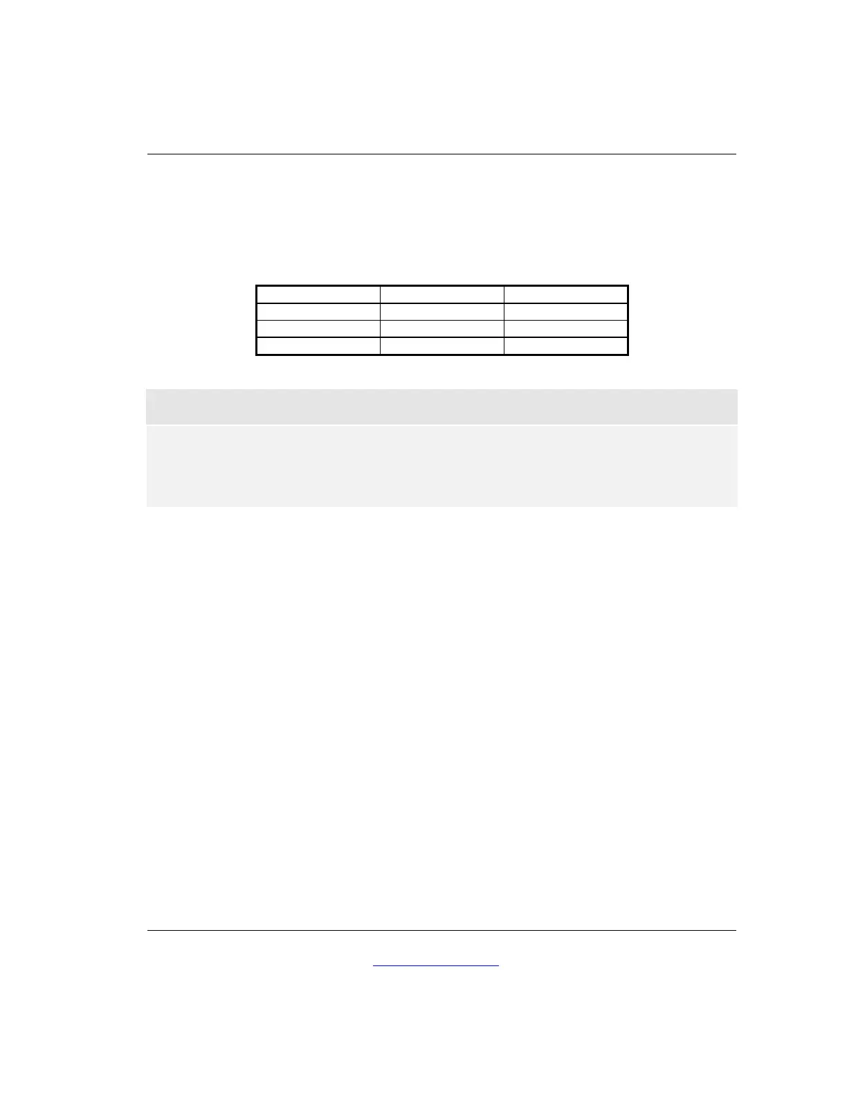
Table 3, Recommended Minimum AC Wire Sizes
Inverter Model 120 VAC Input 120 VAC Output
L2012 10 gauge 12 gauge
L2512 8 gauge 10 gauge
L3012 8 gauge 10 gauge
! Important Precaution
The output side of the inverter’s AC wiring should at no time be connected to
public power or a generator. This condition is far worse than a short circuit. If
the unit survives this condition, it will shut down until corrections are made.
AC output must be isolated from ground to comply with the NEC requirement for neutral-ground
switching. This is easiest to do at the sub-panel by isolating the neutral connector block from
the frame of the subpanel with an appropriate insulator.
Ground Fault Interrupting Outlets (GFCI’s)
Trace Engineering has tested the following GFCI’s and found them to work satisfactorily with our
inverters:
LEVITON 6599
PASS & SEYMOR 1591RI 4A957
ACE Hardware ACE 33238
Some GFCI’s will nuisance trip when used with a modified square wave inverter. Trial is the only
way to tell for sure. On the above listed types, continued nuisance tripping is usually a result of a
wiring problem in the inverter AC output system. Leakage currents present somewhere in the AC
system are causing the GFCI to trip. Make a careful review of the AC wiring layout in your system
and look for possible unwanted ground paths. An error in wiring of the neutral-ground switching
system is a good place to start troubleshooting. Be sure that the AC output neutral is isolated from
the ground. A multimeter may be handy in this troubleshooting procedure.