OPTIONS
Trace Engineering Co. Inc. Tel (360) 435-8826 Part Number 3179
5916 195
th
Street, NE Fax (360) 435-2229 Effective August 6, 1998
Arlington, WA 98223 USA www.traceengineering.com Page
61
Options
Options available for the Legend Series II inverter/charger include a choice of remote controls,
and a battery temperature control.
The RC6 Remote Control
The optional RC6 remote control unit duplicates the Power On/Off Switch on the Legend Series II
inverter/charger. It connects directly to the port labeled Remote Control on the front of the inverter,
using standard phone cable and jacks. Use the included Trace remote cable because it’s a high
quality cable. The wire is custom-made and tinned along its entire length for weather and corrosion
resistance.
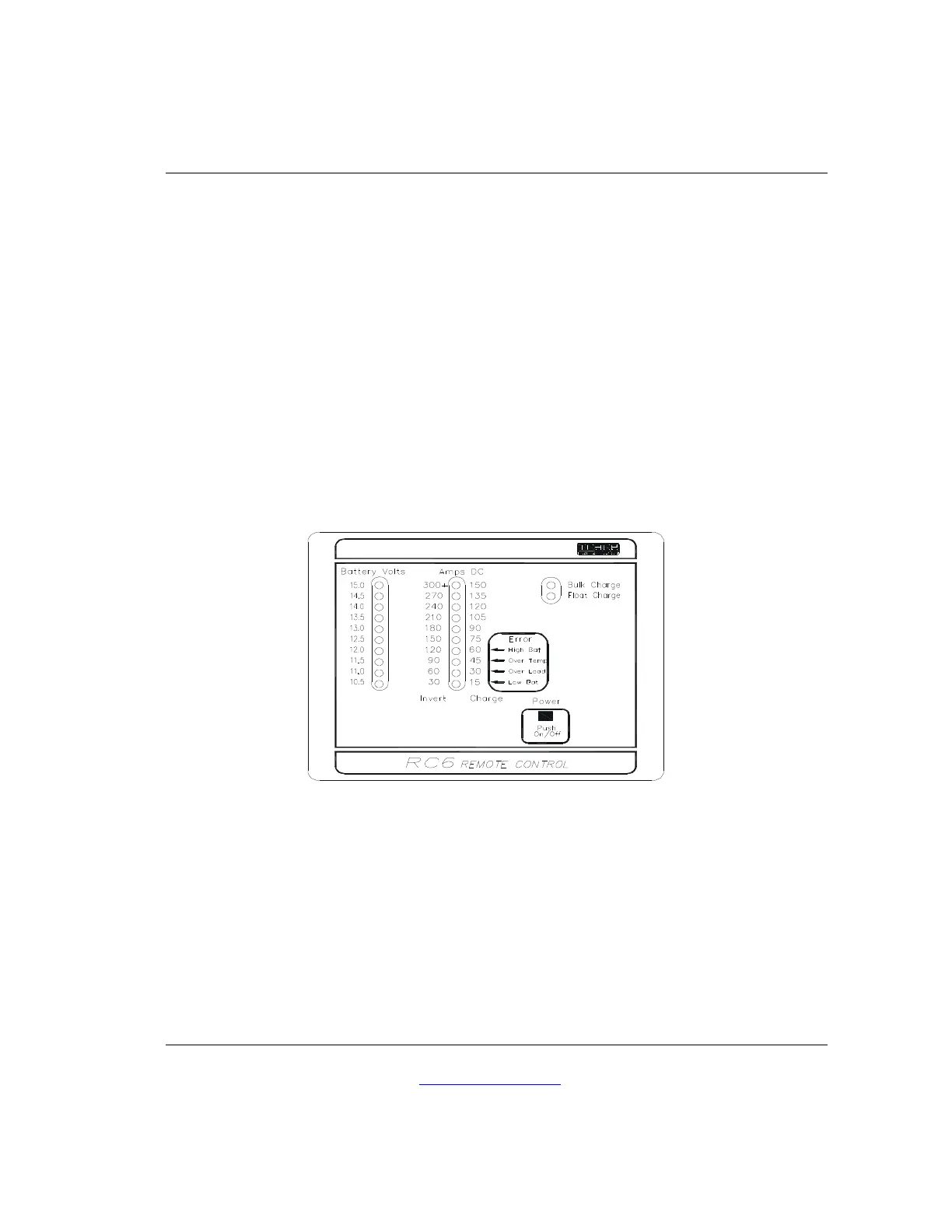
Figure 11, RC6 Remote Control Faceplate Display
The front panel of the RC6 shows the status of several different modes of the inverter, and monitors
the inverter’s output. The lighted bar graph on the far left shows battery voltage from 10.5-15 volts.
The bar graph in the middle of the panel indicates DC amps in either the inverter or charger modes
and will automatically switch between these modes as the inverter changes modes. The four error
lights on the lower right of this graph use the bottom four LED’s of the amperage scale to indicate
four different error conditions: High battery, Low battery, Over temp, and Over load. One of these