INSTALLATION
Trace Engineering Co. Inc. Tel (360) 435-8826 Part Number 3179
5916 195
th
Street, NE Fax (360) 435-2229 Effective August 6, 1998
Arlington, WA 98223 USA www.traceengineering.com
Page
32
The following steps are a basic guideline for installation and connection of the AC wiring into and out
of the inverter.
1. Disconnect the inverter from the battery bank (if already connected), by either removing the DC
side fuse, or opening the DC disconnect. Then remove the AC wiring compartment cover from
the front of the inverter by removing the two screws at the bottom of the cover.
2. If conduit will be utilized (consult code, it may be required in your installation), determine which
knockout(s) will be utilized and remove them from the inverter. Using appropriate conduit
connectors, fasten the conduit to the inverter. Feed all AC wiring through the conduit and into
the inverter AC terminal block (located on the front of the inverter). Be sure to leave yourself
several extra inches of wire to work with. Remember that you need at least two sets of three
conductor wiring, one for AC Hot, neutral, and ground into the inverter, and another for AC hot,
neutral and ground out of the inverter to the loads. Torque all AC terminals to 10 to 15 inch-
pounds.
3. Following the wiring guide shown below, connect the hot (black) and neutral (white) wires from
the AC source (shore power or generator set) to the appropriately labeled terminals in the AC
terminal block. The safety ground (green) should be connected to the terminal stud labeled
“ground” bolted to the floor of the chassis. Repeat the procedure for the AC wiring going to the
AC sub-panel which will power the loads, except connect these wires to the terminals labeled AC
hot out.
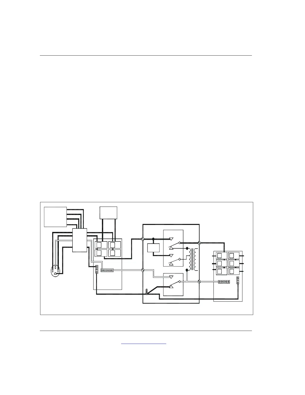
Figure 5, AC Wiring Diagram
GENERATOR
120VAC OR
120/240VAC
HOT
HOT
NEUTRAL
240VAC
AIR
CONDITIONER
EXTERNAL
TRANSFER
RELAY
SWITCH
GROUND
120/240VAC
50 AMP
SHORE
SERVICE
MAIN PANEL
120/240VAC
50 AMP
C
B
CI
FOR 120VAC
CONNECT A
CONNECT A