30WX
TrafiCam with TI (9 wires)
Appendix 2: Output wiring diagram
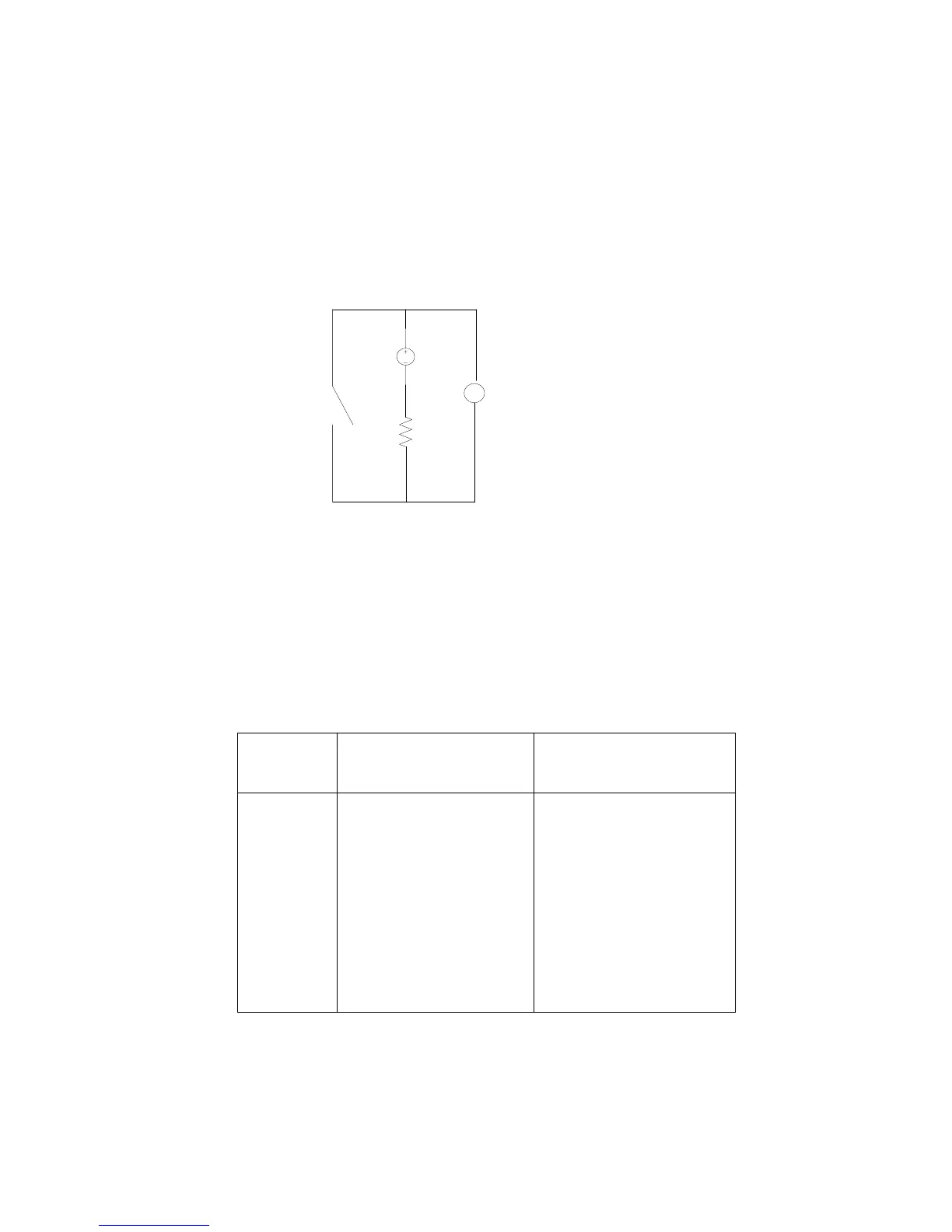
The TrafiCam device has 4 optical coupled dry contacts which serve as outputs. Via TrafiCam PC Tool you can set the
outputs to open or close upon presence detection.
The scheme below illustrates the wiring diagram for the outputs.
5 VDC
COMMON
TrafiCam OUTPUT ANALOG
INPUT
MEASURING
VOLTAGE
R= 10 kO
V
Open: U = 5 V
Closed: U = 0 V
Ir = 0, 5 mA
Pr = 2,5 mW
TrafiCam output wiring diagram
Appendix 3: Colour code of the cable wires
The cables for connection between the TrafiCam device and the interface are not included but can be supplied by
Traficon. Hereafter you find the wire colour code of the cables which Traficon supplies.
Cable
Wire Colour
use with 4TI/1TI
(STP, UV-resistant, 4 wires +
shielding)
use with TI (9 wires)
(STP, UV-resistant, 10 wires +
shielding)
BLUE V-: GROUND V-: GROUND
RED V+: 10-24 VAC/DC V+: 10-24 VAC/DC
GREEN RS-485A RS-485A
YELLOW RS-485B RS-485B
BLACK - COMMON OUTPUT GROUND
GREY - OUTPUT 1
PINK - OUTPUT 2
WHITE - OUTPUT 3
PURPLE - OUTPUT 4
BROWN - -
Colour code of the cable wires