6WX
TrafiCam with TI (9 wires)
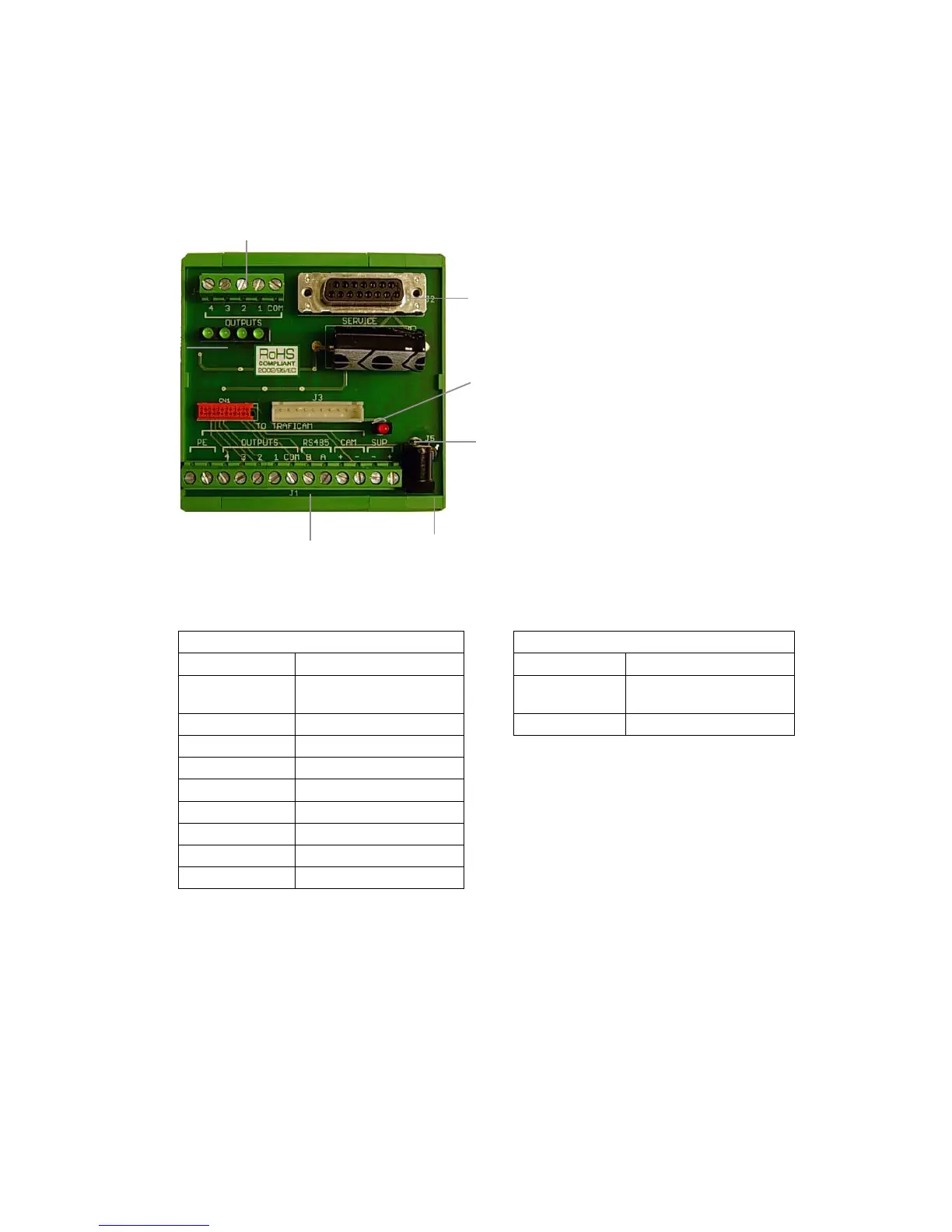
The interface
B
A
J5
J4
J2
J1
J3
A = The LEDs for outputs 1 to 4
B = The power LED
J1 = The connector to the TrafiCam sensor
J2 = The connector to the PC
J3 = The service connector
J4 = The connector to the traffic controller
J5 = The PSU connector
The tables below illustrate the pinout for
connectors J1 and J4.
The TI (9 wires) interface
Pinout of connector J1 Pinout of connector J4
Pin Description Pin Description
CAM - - Power supply Common Common output
(for output 1 to 4)
CAM + + Power supply Output 1 - 4 Output 1 to 4
RS-485A RS-485A
RS-485B RS-485B
Outputs COM Common output ground
Outputs 1 Output 1
Outputs 2 Output 2
Outputs 3 Output 3
Outputs 4 Output 4