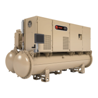
The Trane Agility™ Water-cooled Chiller with Symbio™ Controls is a centrifugal, water-cooled liquid chiller designed for indoor installation. This unit is a completely assembled, hermetic package that is factory-piped, wired, leak-tested, dehydrated, charged, and tested for proper control operation before shipment. The unit ships charged with refrigerant, and its inlet and outlet openings are covered before shipment.
Function Description:
The Agility chiller operates in a cooling mode where liquid refrigerant is distributed along the length of the evaporator and sprayed through small holes to uniformly coat each evaporator tube. The liquid refrigerant absorbs heat from the system water circulating through the evaporator tubes to vaporize. The gaseous refrigerant is then drawn through the suction connection and into the first-stage variable inlet guide vanes and impeller. Compressed gas from the first-stage impeller is discharged through the interstage pipe to the second-stage impeller, where it is further compressed and then discharged into the condenser. Baffles within the condenser shell distribute the compressed refrigerant gas evenly across the condenser tube bundle. Water circulated through the condenser tubes absorbs heat from the refrigerant, causing it to condense. The subcooled liquid refrigerant then flows out of the bottom of the condenser.
The liquid refrigerant is then split: the primary flow is directed through one side of the brazed plate heat exchanger economizer, while a smaller portion passes through an expansion valve, lowering refrigerant pressure and temperature before entering the secondary side of the BPHE as two-phase refrigerant. Heat transfer between the primary and secondary channels in the BPHE results in further subcooling of the primary liquid as it rejects heat to, and consequently superheats, the secondary flow. This additional subcooling effectively increases the overall capacity of the evaporator. The superheated vapor bypasses the evaporator and first stage of compression, with the secondary BPHE flow added prior to the second stage of compression.
Important Technical Specifications:
The Agility chiller models are defined and built using a Product Definition and Selection (PDS) system, which uses a product coding block made up of feature categories and codes to identify all characteristics of a unit. Key specifications include:
- Refrigerant: R-134a or R-513A.
- Evaporator: Designed, tested, and stamped in accordance with ASME Code for refrigerant-side/working-side pressure of 200 psig (1379.0 kPaG). Tubes are 0.75-in. (19.05-mm) diameter, externally finned, internally enhanced seamless copper, and mechanically expanded into carbon steel tube sheets.
- Condenser: Designed, tested, and stamped in accordance with ASME Code for refrigerant-side/working-side pressure of 300 psig (2068.4 kPaG). Tubes are 0.75-in. (19.05-mm) diameter.
- Waterbox Pressure: All water pass arrangements are available with grooved connections (150 psig [1034.2 kPaG] waterside working pressure). Waterside is hydrostatically tested at 1.5X design working pressure. Waterboxes with multiple pass arrangements utilize a baffle designed for a maximum pressure of 20 psid (137.9 kPaD).
- Compressor Motor: Two-stage centrifugal compressor with magnetic bearing modules for levitation and alignment. The motor is a permanent magnet type, cooled by refrigerant gas metered through an orifice or electronic expansion valve.
- Adaptive Frequency Drive (AFD): An electronic motor controller (TR200) that converts AC mains input into a variable AC waveform output to control motor speed/torque. Features include soft start, improved harmonic mitigation (DC link reactor), integrated power fuse, graphical LCD keypad, and factory pre-wiring.
- Controls: Symbio™ 800 microprocessor-based unit control modules provide accurate chilled water control, monitoring, protection, and adaptive limit functions. The Tracer® AdaptiView™ TD12 Operator Interface is a 12-inch touch-sensitive color screen for operating status, performance monitoring, scheduling, and adjustments.
- Uninterruptible Power Supply (UPS): Contains an on-line double-conversion UPS to ensure the compressor's magnetic bearing system continues to function for 90 seconds during a power failure, allowing the compressor to coast to a stop. The UPS (2T5) powers the Symbio™ 800 controls.
- Electrical: All field wiring must conform to NEC and local/state/national codes, using copper conductors only. Unit-mounted AFDs are standard.
- Environmental Conditions (NEMA 1 enclosure): Operating ambient temperature 34°F to 104°F (1.1°C to 40°C), less than 95% relative humidity (non-condensing). Storage temperature -20°F to 122°F (-28.9°C to 50.0°C). Maximum elevation for drive operation is 9842.5 ft (3000 m).
- Insulation: Factory-installed 3/4 in. (19.05 mm) Armaflex® II or equivalent closed cell elastomeric insulation is optional.
Usage Features:
- Rapid Restart™: Designed for quick recovery after power interruptions, allowing the compressor to start within 45 seconds and achieve 80% cooling load in less than 2.5 minutes after power restoration, without needing an external UPS.
- User Interface: The Tracer® AdaptiView™ TD12 display provides logically organized information for operators, service technicians, and owners, including chiller modes, active diagnostics, settings, graphs, and reports. It supports 27 languages.
- Service Tool: Tracer® TU PC-based software is required for software upgrades, configuration changes, and major service tasks, providing a sophisticated interface for technicians.
- Building Automation System (BAS) Integration: Supports BACnet®, Modbus® RTU, and LonTalk® communication protocols for external setpoint/configuration adjustment and monitoring.
- Water Flow Control: Uses ifm efector® flow detection controller and sensor to verify evaporator and condenser water flows.
- Freeze Protection: Requires specific ethylene glycol or propylene glycol solution strengths and adjusted control settings (LRTC, LWTC) for low-temperature environments.
Maintenance Features:
- Scheduled Maintenance:
- Weekly: Log chiller, check evaporator and condenser pressures.
- Monthly: Review operating log, clean water strainers.
- Annual: Perform all weekly/monthly procedures, leak check, inspect safety controls and electrical components (magnetic bearing controller, UPS), inspect piping, clean in-line strainers, clean and repaint corroded areas, inspect relief valve vent piping, inspect condenser tubes for fouling.
- Every 3 years: Nondestructive tube test for condenser and evaporator tubes.
- Every 5 years: Drain and replace drive cooling fluid, replace fluid strainer.
- Annually: Perform a fluid pH test for drive cooling loop.
- Drive Cooling System: Rejects heat through a hybrid air and fluid heat sink. Includes a wet rotor circulation pump, thermal expansion tank, vented-pressure cap, and particulate strainer.
- Condenser Cleaning: Mechanical or chemical cleaning methods for fouled tubes.
- Waterbox Removal: Instructions for safe removal and reassembly, including rigging shackles and torque specifications. New O-rings are required for reassembly.
- AFD Maintenance: Periodic maintenance and inspections (1-12 months) of the AFD, including visual inspection (power removed) of components, wiring, and cleanliness, and operational inspection (power applied) of cooling fans, fault codes, and configuration settings.
- Safety Precautions: Emphasizes lockout/tagout procedures, proper PPE, and capacitor discharge before servicing electrical components.
- Troubleshooting: Diagnostic messages assist operators in identifying problems.