52
HDWA-SVX002C-EN
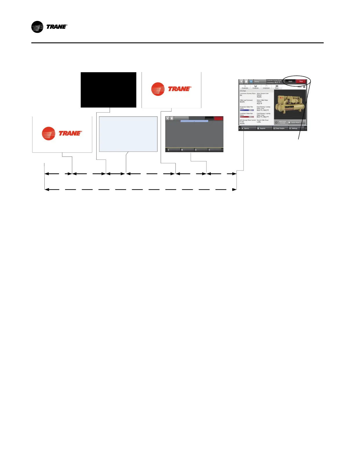
Figure 35. Sequence of operation: AdaptiView power up
*Display will show
either Auto or Stop
button as “active”
(depressed) once
it is ready
10 Sec
First Trane Logo
Grey Screen
Second Trane Logo - Loading
User Interface Template...
Black Screen
Loading Data...
Display Ready
20 Seconds
30 Seconds
25 Seconds
Operator Display Boot Up and Load - 105 sec Total to Display Ready
15 Sec
5 Sec
White Screen
In the following diagrams:
• The time line indicates the upper level operating mode,
as it would be viewed in the Tracer® AdaptiView™.
• The shading color of the cylinder indicates the software
state.
• Text in parentheses indicates sub-mode text as viewed
in the Tracer® AdaptiView™.
• Text above the time line cylinder is used to illustrate
inputs to the Symbio™ 800. This may include user
input to the AdaptiView™ touch screen, control inputs
from sensors, or control inputs from a generic BAS.
• Boxes indicate control actions such as turning on
relays, or moving the inlet guide vanes.
• Smaller cylinders under the main cylinder indicate
diagnostic checks.
• Text outside a box or cylinder indicates time-based
functions.
• Solid double arrows indicate fixed timers.
• Dashed double arrows indicate variable timers.
Power Up
“Software Operation Overview Diagram,” p. 51 includes an
illustration of Tracer® AdaptiView™ during a power up of
the Symbio™ 800. This process takes from 30 to
50 seconds depending on the number of installed options.
Start-up and Shutdown
 Loading...