20
HDWA-SVX002C-EN
NOTICE
Wiring Damage!
Damage to unit wiring could result in equipment
failure.
Care must be taken during rigging, assembly and
disassembly to avoid damaging unit wiring.
Standard Chiller Lift
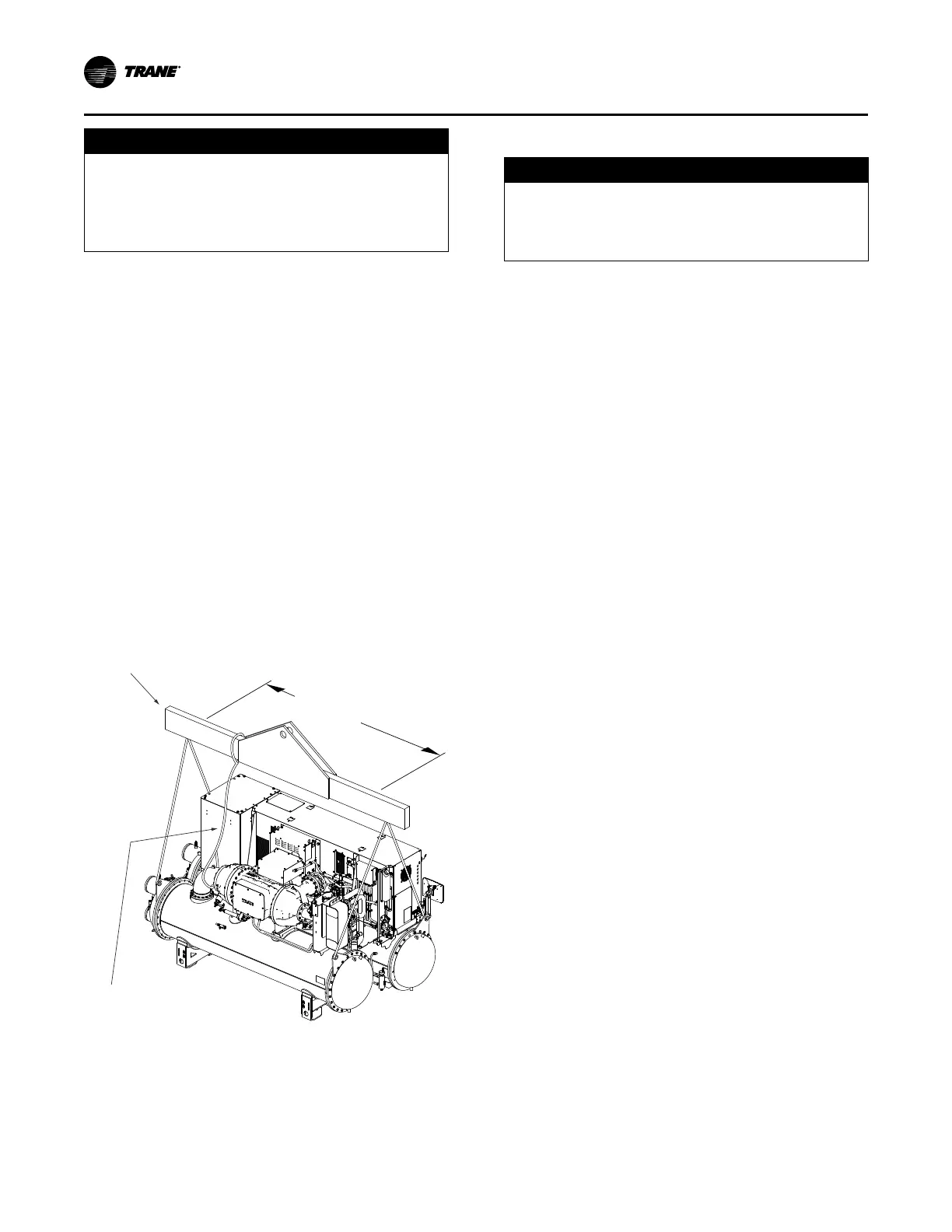
1. Insert rigging shackles at the points indicated in the
following figure. A 1.25 in. (31.8 mm) diameter lifting
hole is provided at each of these points.
2. Attach the lifting chains or cables.
3. After the lifting cables are in place, attach a safety
chain or cable between the first-stage of the
compressor and the lifting beam.
Important: There should NOT be tension on this safety
cable; the cable is used only to prevent the
unit from rolling during the lift.
4. Position isolator pads beneath the chiller feet (refer to
“Unit Isolation,” p. 20 for instructions).
5. Once the isolators are in place, lower the chiller—
working from end to end—in small increments to
maintain stability.
6. When lift is complete, detach the rigging shackles and
safety chain.
Figure 9. Typical rigging arrangements
10 to 12 ft (3.0 to 3.7 m)
6 in. (15.2 cm) effective length
Lifting beam
Safety chain
Special Lift Requirements
NOTICE
Equipment Damage!
Moving the chiller using a fork lift could result in
equipment or property-only damage.
Do not use a fork lift to move the chiller!
If the chiller cannot be moved using a standard chiller lift,
consider the following:
• When job site conditions require rigging of the chiller at
an angle greater than 45° from horizontal (end-to-end),
the unit may require removal of the compressor.
Contact Trane or an agent of Trane specifically
authorized to perform start-up and warranty of Trane
®
products regarding the disassembly and reassembly
work. For more information, refer to “Factory Warranty
Information,” p. 3.
Note: Disassembly and reassembly work includes
removing the compressor from the unit. Contact
Trane or an agent of Trane specifically
authorized to perform start-up and warranty of
Trane
®
products for specific rigging instructions.
Do NOT attempt to rotate the chiller onto its side.
• When lifting the chiller is either impractical or
undesirable, machinery dollies should be placed under
the supports; then push or pull the unit across a smooth
surface. Should the chiller be on blocks, it is not
necessary to remove the blocks from the chiller before
moving it into place.
• Use care on uneven surfaces. Piping in the center of
the unit is within 1/2 in. (12.7 mm) of the ground.
Unit Isolation
To minimize sound and vibration transmission through the
building structure and to ensure proper weight distribution
over the mounting surface, Trane recommends installing
isolation padding under the chiller feet. For seismic
installations, refer to the specific installation details
provided by the foundation designer.
Note: Isolation pads are provided with each chiller.
Specific isolator loading data is provided in the unit
submittal package. If necessary, contact your local Trane
sales office for further information.
Important: When determining placement of isolation pads,
remember that the control panel side of the
unit is always designated as the front side of
the unit.
Isolation Pads
When isolation pads are used, place them under each of
the eight individual mounting points. The pads may be cut
to suit the application, but should cover the entire face of
the support.
Installation: Mechanical
 Loading...

