30
HDWA-SVX002C-EN
thermometers, flexible connectors, and any removable pipe
spools.
Ensure that the evaporator water piping is clear; check it
after the chilled water pump is operated but before initial
chiller start-up. If any partial blockages exist, they can be
detected and removed to prevent possible tube damage
resulting from evaporator freeze-up or erosion.
For condenser and evaporator connections, arrange the
water piping so that the water supply enters the shell at the
lower connection and exits from the top connection.
Operational problems may result if this piping is not correct.
For applications that include an “infinite source” or
“multiple-use” cooling condenser water supply, install a
valved bypass “leg” (optional) between the supply and
return pipes. This valved bypass allows the operator to
short-circuit water flow through the cooling condenser
when the supply water temperature is too low.
Water Piping Connections
All standard units use grooved-pipe connections. These
are grooved-end NSP (Victaulic® style) pipe connections.
Flanged connections are optional.
Piping joined using grooved type couplings, like all types of
piping systems, requires proper support to carry the weight
of pipes and equipment. The support methods used must
eliminate undue stresses on joints, piping, and other
components, allow movement where required, and provide
for any other special requirements (i.e., drainage, etc.).
Note: If needed, plug-type sensor extension cables are
available for purchase from Trane Parts Service.
These sensor extension cables may be necessary if
the waterboxes are changed or if the temperature
sensors are moved out into the unit piping for better
mixed temperature readings.
Table 11. Water connection pipe sizes
EVSZ/CDSZ
Nominal Pipe Size
2 Pass
in. mm
020 6 168.3
040 8 219.1
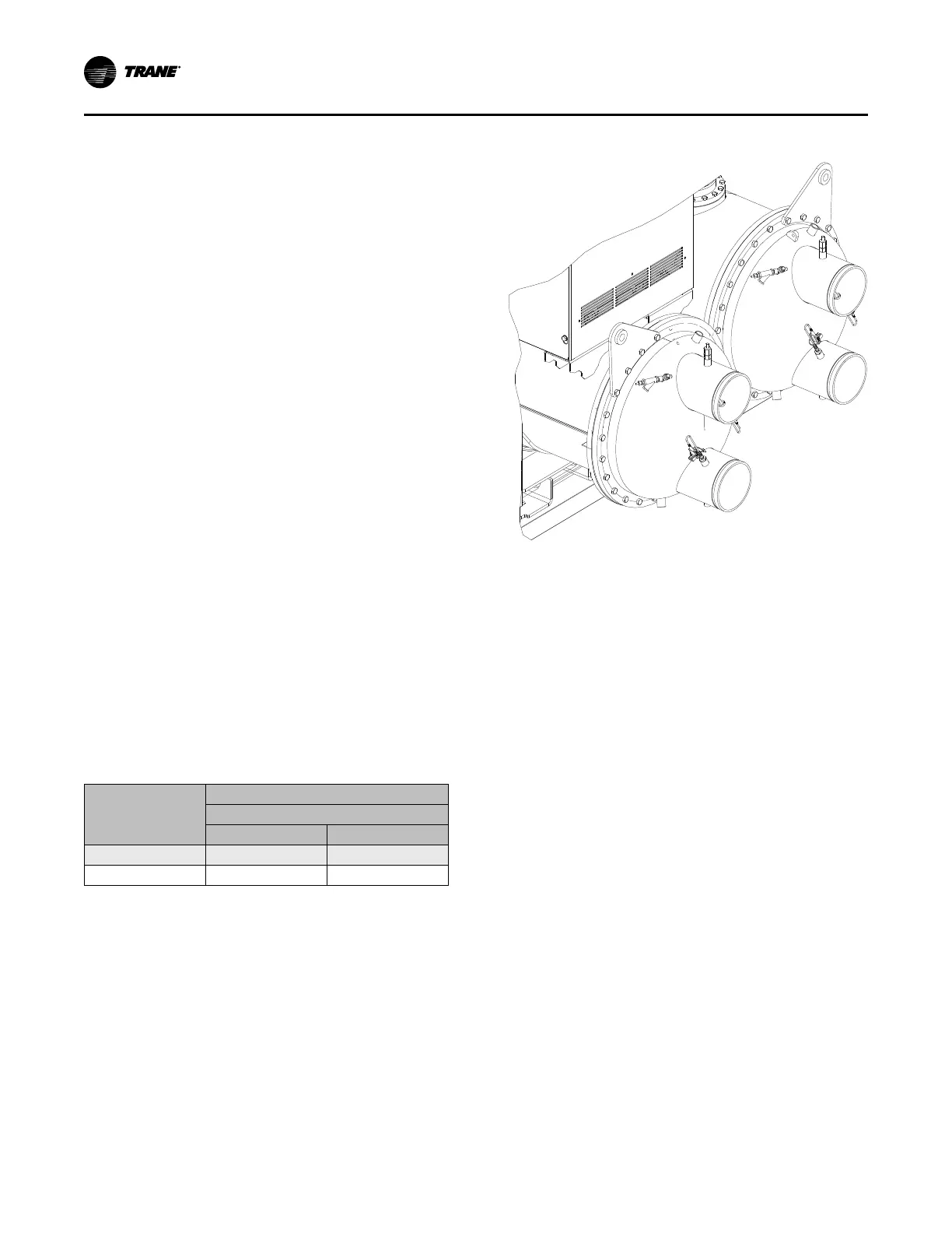
Figure 20. Typical grooved pipe connection
Waterbox Locations
Note: Do NOT interchange evaporator and condenser
waterboxes. Supply evaporator waterbox and
tubesheet contain match marks to aid in identifying
matching shells and waterboxes.
If removal of waterboxes is necessary, refer to “Waterbox
Removal,” p. 68.
If the waterboxes on any of the shells are exchanged end-
for-end, be sure to reinstall them right-side up to maintain
the correct baffle arrangements. Use a new gasket with
each waterbox cover.
Reversing Waterboxes
All waterboxes can be reversed end-for-end. Refer to
“Waterbox Removal,” p. 68 for detailed waterbox removal
instructions.
Remove sensors from wells before removing waterbox.
Do NOT rotate waterboxes.
Complete the waterbox switch and replace sensors.
Installation: Water Piping
 Loading...

