HDWA-SVX002C-EN
49
Operating Principles
General Requirements
Operation and maintenance information are covered in this
section. By carefully reviewing this information and
following the instructions given, the owner or operator can
successfully operate and maintain the chiller. If mechanical
problems do occur, however, contact a Trane service
technician to ensure proper diagnosis and repair of the
unit.
Important:
• Although Agility™ chillers can operate
through surge, it is NOT recommended to
operate them through repeated surges
over long durations. If repeated surges of
long durations occur, contact your Trane
Service Agency to resolve the issue.
• Agility™ are selected, designed, and built
for a particular set of design conditions.
Operation outside of design conditions
may result in improper operation. Refer to
chiller selection for minimum unloading.
Refrigeration Cycle
When in the cooling mode, liquid refrigerant is distributed
along the length of the evaporator and sprayed through
small holes in a distributor (i.e., running the entire length of
the shell) to uniformly coat each evaporator tube. Here, the
liquid refrigerant absorbs enough heat from the system
water circulating through the evaporator tubes to vaporize.
The gaseous refrigerant is then drawn through the suction
connection and the first-stage variable inlet guide vanes,
and into the first-stage impeller.
The unit is equipped with a semi-hermetic, direct-drive,
two-stage, centrifugal compressor that includes inlet guide
vanes for capacity control. The Adaptive Frequency™
Drive (AFD) provides capacity control with lower speeds.
Compressed gas from the first-stage impeller is discharged
through the interstage pipe to the second-stage impeller.
Here, the refrigerant gas is again compressed, and then
discharged into the condenser. Baffles within the
condenser shell distribute the compressed refrigerant gas
evenly across the condenser tube bundle. Water circulated
through the condenser tubes absorbs heat from the
refrigerant, causing the refrigerant to condense. The
subcooled liquid refrigerant then flows out of the bottom of
the condenser.
The liquid refrigerant is then split such that the primary flow
is directed through one side of the brazed plate heat
exchanger economizer, while a significantly smaller portion
of the flow passes through an expansion valve, lowering
refrigerant pressure and temperature before entering the
secondary side of the BPHE as two-phase refrigerant. The
heat transfer between the primary and secondary channels
in the BPHE results in further subcooling of the primary
liquid as it rejects heat to, and consequently superheats,
the secondary flow. The additional subcooling of the liquid
prior to expansion through the main electronically-
controlled valve effectively increases the overall capacity of
the evaporator. In addition, the superheated vapor
bypasses the evaporator and first stage of compression
(the secondary BPHE flow is added prior to the second
stage of compression).
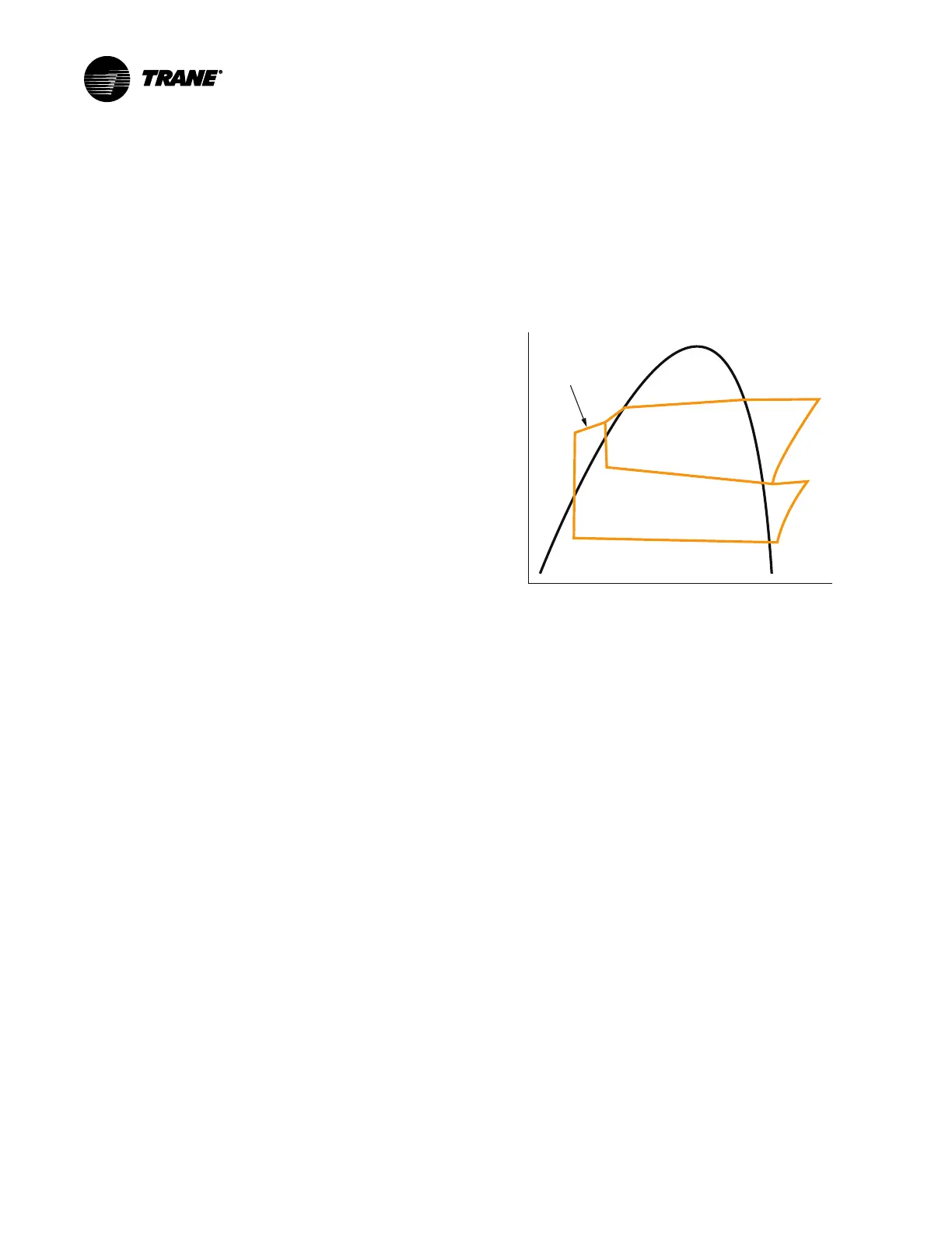
Figure 33. Refrigerant flow
Pressure
Enthalpy
4
3
5
7
6
2
8
1
9
Primary
Condenser
Secondary
Evaporator
Compressor
Second Stage
Compressor
First Stage
Compressor Motor
Two magnetic bearing modules levitate and align the
rotating assembly. The motor is permanent magnet type
and is cooled by refrigerant gas sourced from the
interstage pipe, metered through an orifice or electronic
expansion valve, and routed through the bearing modules
and motor windings.
Adaptive Frequency Drive
An Adaptive Frequency™ Drive (AFD) and control panel is
provided on every chiller. Microprocessor-based unit
control modules (Symbio™ 800) provide for accurate
chilled water control as well as monitoring, protection, and
adaptive limit functions. The "adaptive" nature of the
controls intelligently prevents the chiller from operating
outside of its limits, or compensates for unusual operating
conditions, while keeping the chiller running rather than
simply tripping due to a safety concern. When problems do
occur, diagnostic messages assist the operator in
troubleshooting.
Uninterruptible Power Supply
Agility™ chillers contain an on-line double-conversion
Uninterruptible Power Supply (UPS) to ensure that the
compressor’s magnetic bearing system continues to
function in the event of an power failure. The UPS (2T5)
provides power to the Symbio™ 800 controls for 90
 Loading...

