HDWA-SVX002C-EN
39
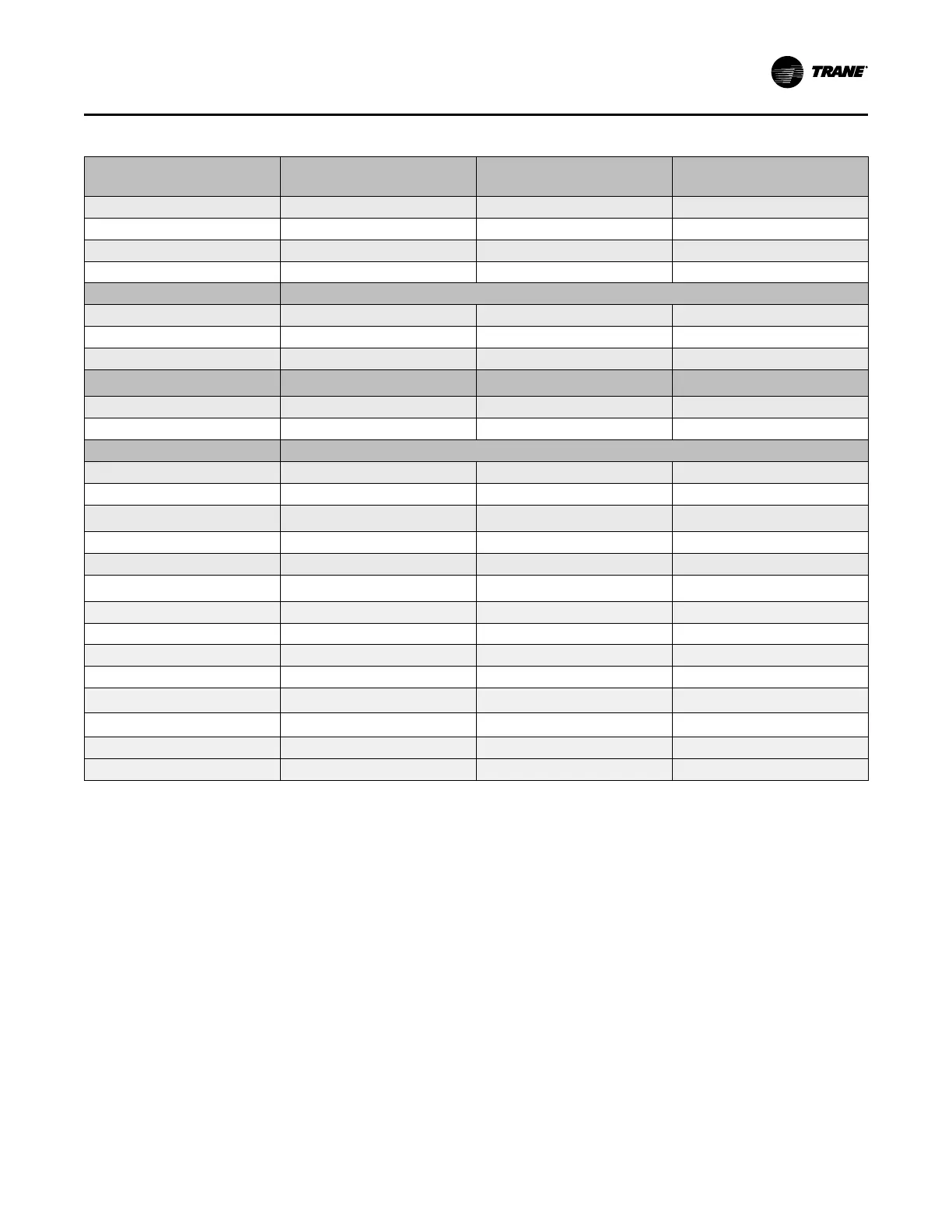
Table 19. Unit control panel wiring 120 Vac
Standard Control Circuits: Unit
Control Panel Control Wiring
(120 Vac)
Unit Control Terminations
Input or Output Type
Contacts
Evaporator Water Flow Switch
1K11-J3-1 to 2
Binary Input Normally Open, Closure with Flow
Condenser Water Flow Switch 1K11-J2-1 to 2
Binary Input Normally Open, Closure with Flow
Evaporator Water Pump Control
1K12-J2-4 to 6
Binary Output Normally Open
Condenser Water Pump Control
1K12-J2-1 to 3
Binary Output Normally Open
Optional Control Circuits (120 Vac) Note: Defaults are factory programmed; alternates can be selected at start-up using the service tool.
Maximum Capacity Relay Output
1K14-J2-4
Binary Output Normally Open
Head Relief Request Relay Output
1K14-J2-4 to 6
Binary Output Normally Open
Ice Building Indicator
1K15-J2-1 to 3
Binary Output Normally Open
Standard Low Voltage Circuits (Less
than 30 Vac)
(a)
Unit Control Panel Terminations
Input or Output Type
Contacts
External Auto Stop Input
1K4-J2-1 to 2
Binary Input Closure Required for Normal Operation
Emergency Stop Input
1K4-J2-3 to 4
Binary Input Closure Required for Normal Operation
Optional Low Voltage Circuits
External Base Loading Enable Input
1K9-J2-1 to 2
Binary Input Normally Open
External Hot Water Control Enable Input
1K9-J2-3 to 4
Binary Input Normally Open
External Ice Machine Control Enable
Input
1K3-J2-1 to 2
Binary Input Normally Open
Condenser Refrigerant Pressure
1K7-J2-4 to 6
Analog Output
2–10 Vdc
Chiller % Capacity Output
1K7-J2-1 to 3
Analog Output
2–10 Vdc
Evaporator/Condenser Differential
Pressure Output
1K7-J2-4 to 6
Analog Output
2–10 Vdc
External Demand Limit Setpoint Input
1K6-J2-2 to 3
Analog Input
2–10 Vdc, or 4–20 mA
External Chilled Water Setpoint Input
1K6-J2-5 to 6
Analog Input
2–10 Vdc, or 4–20 mA
External Base Loading Setpoint Input
1K8-J2-2 to 3
Analog Input
2–10 Vdc, or 4–20 mA
Generic Refrigerant Monitor Input
1K8-J2-5 to 6
Analog Input
2–10 Vdc, or 4–20 mA
Outdoor Air Temperature Sensor
Inter-processor Communication (IPC)
Bus Connection and Sensor—4BT9
Communication and Sensor
LON Interface 1K25
Communication to Tracer
or LonTalk
(As Ordered; See Sales Order)
BACnet or MODBUS 1K20–P1 Communication to BACnet or MODBUS
(As Ordered; See Sales Order)
Air-Fi® 4K4 Wireless Communication to Tracer
Note: All wiring to be in accordance with National Electrical Code (NEC) and any local codes.
(a)
Standard low-voltage circuits (less than 30 Vac) must be separated from 120 Vac or higher wiring.
Sensor Circuits
All sensors are factory-installed except the optional outdoor
air temperature sensor, and Wireless modules (refer to the
following figure for sensor locations). This sensor is
required for the outdoor air temperature type of chilled
water reset. Use the following guidelines to locate and
mount the outdoor air temperature sensor. Mount the
sensor probe where needed; however, mount the sensor
module in the control panel.
Electrical Requirements
 Loading...