BAS-SVU025A-EN 41
LEDs and the 7-Segment Display
This section describes how to interpret the activity of the LEDs and the 7-segment display on the
Tracer SC.
Powering Up/Powering Down the Tracer SC
To power up theTracer SC, press the power button (see Figure 1).
All LEDs illuminate and the following sequence flashes on the 7-segment display: 8, 7, 9*, 5, 4,
L, dancing dash pattern.The dancing dashes persist while theTracer SC is operating normally
(see “Interpreting the 7-Segment Display,” p. 43).
* 7-segment 6 was changed to 9 to indicate the new boot file had been successfully applied.
To power down theTracer SC, press the power button.The 7-segment display performs a shut-
down sequence (3, -, 2, -, 1, -) before theTracer SC power s down.
The LEDs and the 7-Segment Display
The LEDs and the 7-segment display on theTracer SC indicate the operation and communication
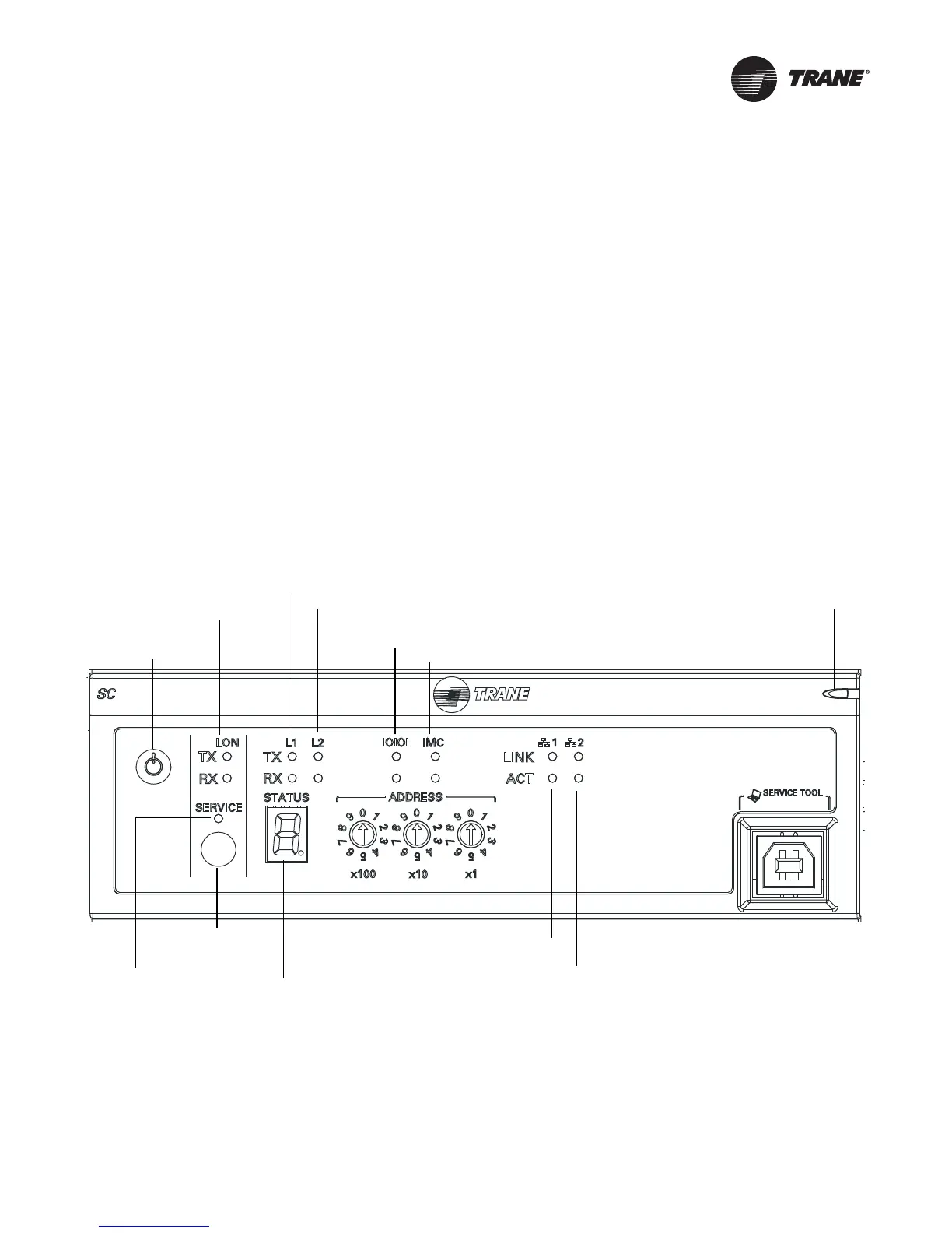
status of theTracer building automation system. Figure 1 shows their locations on the front of the
controller.
Figure 1. Location of the LEDs and the 7-segment display on the Tracer SC
7-segment display
BACnet MS/TP link 1 communication LEDs
Ethernet 1 LEDs
BACnet MS/TP link 2 communication LEDs
LonTalk communication LEDs
LonTalk service LED
Ethernet 2 LEDs
Power button
Status LED
EIA-232 LEDs
IMC LEDs
LonTalk service pin