Unit Start Up
RT-SVX36K-EN 151
decrease the amount of air entering the combustion
chamber. Refer to Figure 123, p. 154 for the location of
the combustion air damper.
8. Recheck the oxygen and carbon dioxide levels after
each adjustment. After completing the high-fire
checkout and adjustment procedure, the low-fire
setting may require adjusting.
Low-Fire Adjustment (500 MBH, 850 & 1,000
MBH only)
1. Use theTEST initiation procedures outlined in the
previous section to operate the furnace in the low-fire
state (1st Stage).
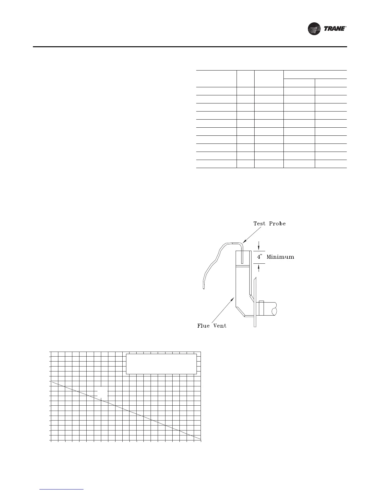
2. Use a carbon dioxide analyzer and measure the
percentage of carbon dioxide in the flue gas. Refer to
the illustration in Figure 119, p. 151.Take several
samples to assure that an accurate reading is obtained.
Refer to Figure 120, p. 151 for the proper carbon
dioxide levels. If the measured carbon dioxide level is
within the listed values, no adjustment is necessary. A
carbon dioxide level exceeding the listed range
indicates incomplete combustion due to inadequate
air or excessive gas.
3. Check the manifold gas pressure by using the manifold
pressure port on the gas valve. Refer to Figure 120 for
the required manifold pressure during low-fire
operation. If it needs adjusting, remove the cap
covering the low-fire adjustment screw on the gas
valve. Refer to Figure 120 for the adjustment screw
location.Turn the screw clockwise to increase the gas
pressure or counterclockwise to decrease the gas
pressure.
Note: Do not adjust the combustion air damper while the
furnace is operating at low-fire.
4. Check the carbon dioxide levels after each adjustment.
5. Press the STOP key at the Human Interface Module in
the unit control panel to stop the system operation.
Table 61. Recommended manifold pressures and CO
2
levels during furnace operation (see notes)
Manifold
Furnace Stage MBH Firing Rate %CO
2
Pressure
High-Fire 235 100% 8.5 - 9.5 3.0 - 3.5
Low-Fire 117 50% 6.0 - 7.0 0.9
High-Fire 350 100% 8.5- 9.5 3.0 - 3.5
Low-Fire 175 50% 6.0 - 7.0 0.9
High-Fire 500 100% 8.5 - 9.5 3.0 - 3.5
Low-Fire 250 50% 6.0 - 7.0 1.25
High-Fire 850 100% 8.5 - 9.5 3.0 - 3.5
Low-Fire 500 50% 6.0 - 7.0 1.25
High-Fire 1000 100% 8.5 - 9.5 3.0 - 3.5
Low-Fire 500 50% 6.0 - 7.0 1.25
Note:
1. Manifold pressures are given in inches w.c.
2. High fire manifold pressure is adjustable on all heaters.
3. Low fire manifold pressure is non-adjustable on 235 MBH and 350
MBH heaters.
Figure 119.Flue gas carbon dioxide and oxygen
measurements
Figure 120. Natural gas combustion curve (ratio of oxygen to carbon dioxide in percent)
0
1
2
3
4
5
6
7
8
9
10
11
12
13
14
15
16
17
18
0123456789101112131415161718192021
Percent Oxygen
Percent Carbon Dioxide
Curve Fuel
A = 1,000 BTU per cu. ft.
of Natural Gas.
A