Installazione
Funzionamento
Manutenzione
Unità ad alta precisione Jupiter
Unità a espansione diretta
JDAC / JUAC / JDAV / JUAV / JDWC / JUWC / JDWV / JUWV
Taglie: 0115 – 0125 – 0133 – 0135 – 0150 – 0160
Unità ad acqua refrigerata
JDCC / JUCC / JDCV / JUCV
Taglie: 0020 – 0025 – 0030 – 0040 – 0060
PKG-SVX24B-IT
2700A - 3400A - 4000A - 4300A
JD./JU.A-W (C-V)
0115B - 0125B
JD./JU.A-W (C-V)
0115A - 0125A - 0133A - 0135A - 0150A - 0160 A
JD./JU.C-W (C-V)
0020B - 0025B - 0030B - 0040B - 0060B
Once the connections have been made, pour water into the
condensate drain until the siphon inside the unit is full.
The external drainage tube must be siphoned to avoid
unpleasant odours and an overow of the water from the
tray of the humidier. Maintain a minimum slope of 1%
downstream of the siphon.
Once the connections have been made, pour water into
the condensate collection tray of the Jupiter unit and in
the condensate collection tray of the humidier until both
siphons are full.
U7
U4
Connection to the humidier (optional) and to the drains
of the building
WARNING! The water discharged from the
humidier is at a very high temperature. The
drainage tube has to withstand high temperatures
(at least 100°C) and must be kept away from
electrical cables.
Connect the drainage tube of the unit to the collection tray
(U4) of the humidier.
Connect the drainage tube of the humidier (U7) to the
drains of the building using a rubber or plastic tube, which
is resistant to high temperatures (minimum 100 °C) with an
internal diameter of 22 mm.
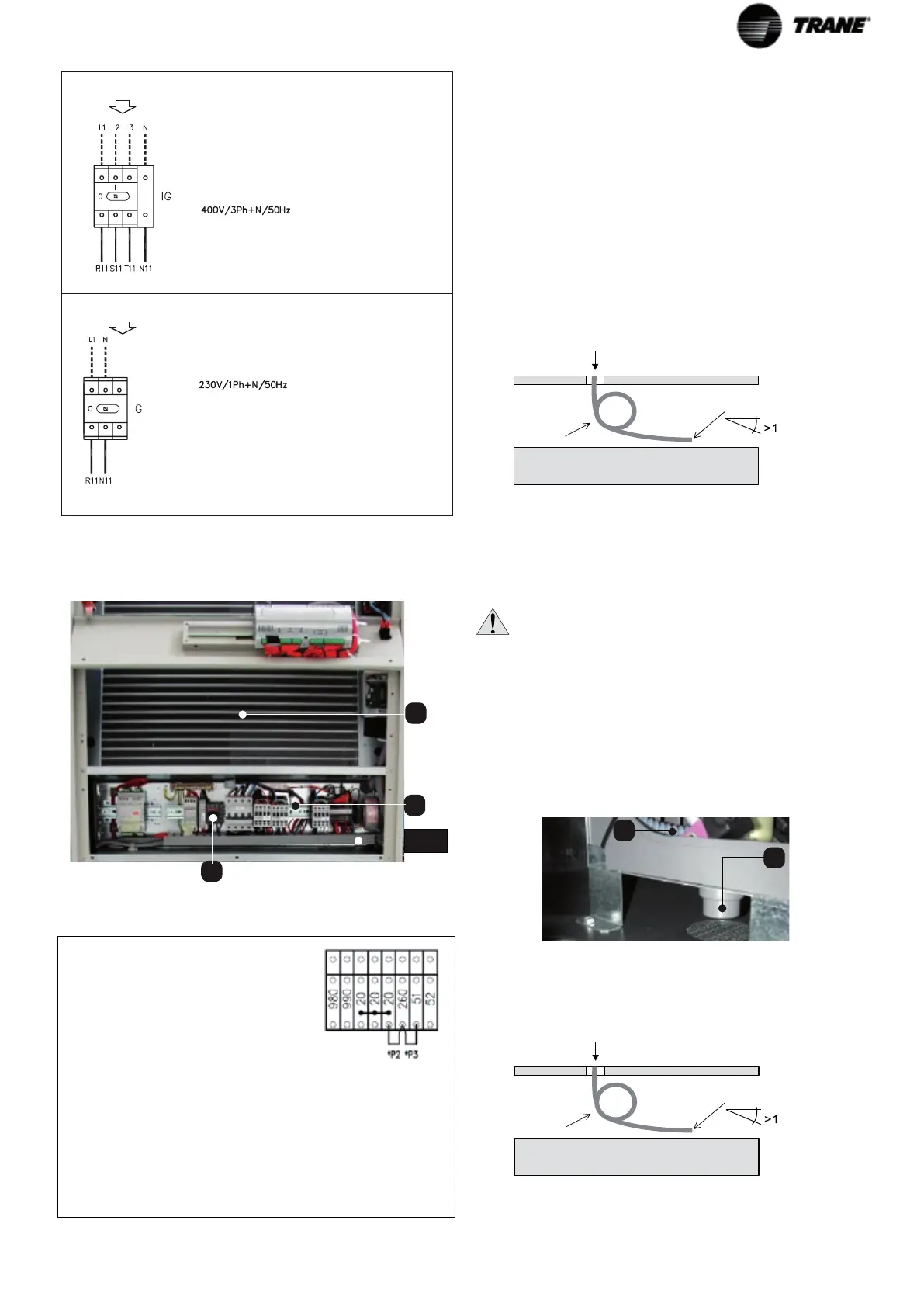
To connect the auxiliary connections to the terminal board,
carry out the following procedures:
• pass the cables through the power supply cable inlet
D7b;
• refer to the wiring diagram and carry out the connection
to the terminal board.
DIGITAL CONFIGURABLE INPUTS
Terminal board 51-20
- User
- ON - OFF Remote
- Flooding sensor (SAS)
- Tools (ATA-BTA-AUA-BUA)
Terminal board 52-20
- User
- ON-OFF Remote
- Fire-smoke (SFF)
Remote signalling
Terminal board 980 - 990
- Signalling of the state of the unit (CV)
G12
D
D7b/d
D5
*P2: REMOVE WHEN “SAS” IS INSTALLED
*P3: REMOVE WHEN “ATA-BTA-AUA-BUA” ARE
INSTALLED
Connection to the drains
The condensed water drains from the tray through a
siphoned exible tube tted in the unit.
If the conditioner is tted with a humidier, the condensate
drain tray and the humidier drain connection must be
connected to the drains of the building.
Direct connection to the drains of the building
Connect the drainage tube of the unit to the drains of the
building using a rubber or plastic tube with an internal
diameter of 25 mm.
The external drainage tube must be siphoned in order to
avoid unpleasant odours. Maintain a minimum slope of 1%
downstream of the siphon.
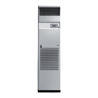
POWER SUPPLY CABLE
(at customers at care)
POWER SUPPLY CABLE
(at customers at care)
Drain
%
Siphon
Minimum slope
Drain
%
Siphon
Minimum slope
Drain
Drain
Siphon
Siphon
Minimum slope
Minimum slope
 Loading...


