Installazione
Funzionamento
Manutenzione
Unità ad alta precisione Jupiter
Unità a espansione diretta
JDAC / JUAC / JDAV / JUAV / JDWC / JUWC / JDWV / JUWV
Taglie: 0115 – 0125 – 0133 – 0135 – 0150 – 0160
Unità ad acqua refrigerata
JDCC / JUCC / JDCV / JUCV
Taglie: 0020 – 0025 – 0030 – 0040 – 0060
PKG-SVX24B-IT
Code Description Opening Differential Re-set
AP
High pressure
switch
40,5 bar
(opening)
-
Manual
Reset
TSR
First emergency
safety
thermostat
310 °C
(opening)
-
Manual
Reset
TSRA
Second
emergency
safety
thermostat
328 °C
(opening)
-
Manual
Reset
R410A
Setting the regulation and safety devices
After starting up the unit, set the following set points (see
the microprocessor control manual):
• Room temperature (cooling and heating set point);
• Re l ative room h u midity (humidi ficatio n and
dehumidication set point);
• Dirty lter differential pressure switch: see paragraph
“Setting the dirty lter sensor”.
The settings of the safety devices must not be modied.
Maximum and minimum water temperatures
The maximum and minimum water temperatures for chilled
water circuits and for hot water re-heat circuits are: 5°C ÷
90°C.
The accepted maximum amount of ethylene glycol is 0%.
Setting the pressostatic valve (optional on
chilled water cooled models only)
The pressostatic valve, by controlling the water flow,
prevents the condensing pressure falling too low and at the
same time minimises water consumption. When necessary,
set the pressostatic valve by turning the regulation knob
(the pressure increases when turning it clockwise) until
the condensation pressure stabilizes to recommended*
checking the pressure with a gauge tted to the pressure
tapping of the compressor discharge valve.
* R410A :pressure 26 bar = temperature 45°C
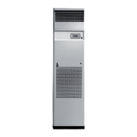
Setting the air ow sensor
The FS differential pressure switch intervenes if the fan (or
one of the fans) stops working.
The factory set point of the FS differential pressure switch
is at 0.5 mbar (= 50Pa).
As the difference in pressure between the suction and
discharge of the fans depends on the air ow, it may be
necessary to calibrate the instruments after installation,
checking that the contact closes when the fans are in
operation.
To set the FS pressure switch, carry out the following
procedure:
• simulate a fan fault by stopping a fan; check that the
pressure switch intervenes;
• if the pressure switch does not intervene, gradually
increase the setting until the pressure switch switches
off:
- using an adjustment screw, set the differential pressure
switch on a scale (from 0.5 to 4.0 mbar - from 50 to
400 Pa).
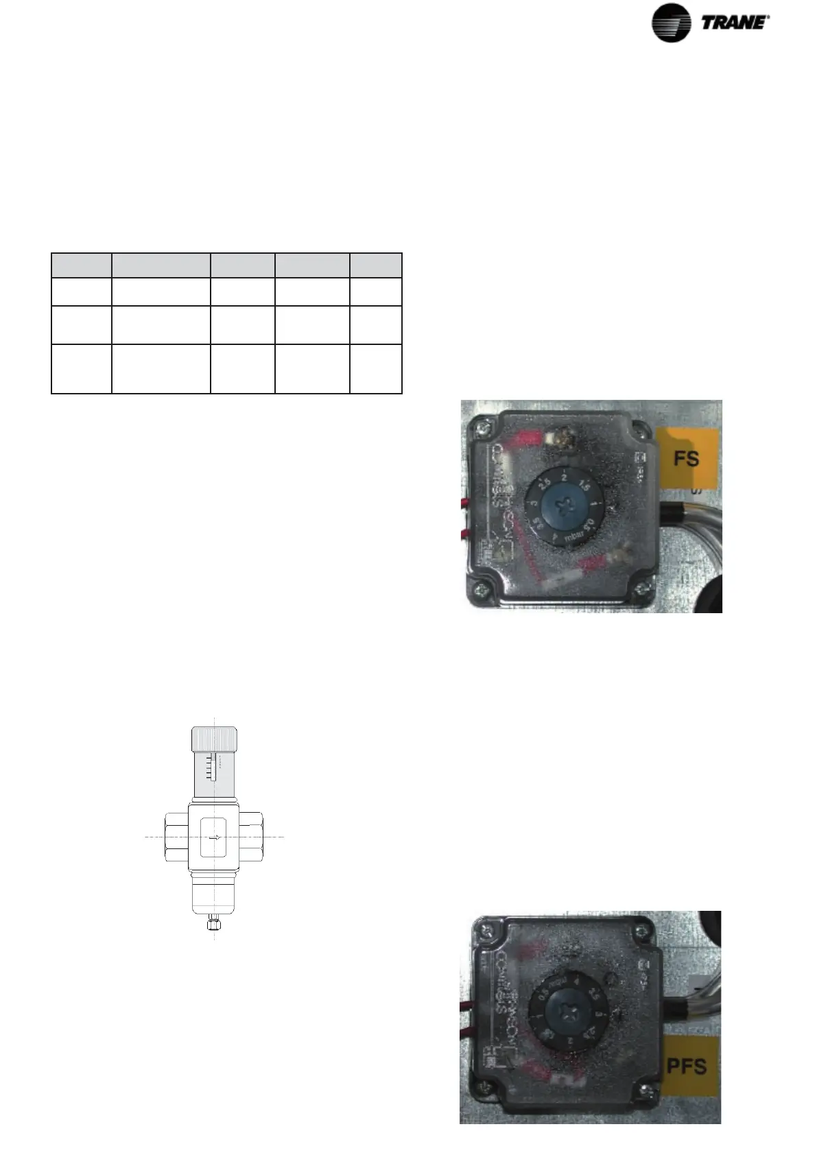
Setting the dirty lter sensors
The PFS differential pressure switch is set according to
the loss of load dependent on the dirt inside the lters and
the air ow.
The PFS differential pressure switch must be set at 3 mbar
(=300 Pa).
To set the PFS pressure switch, carry out the following
procedure:
• gradually cover the surface of the air lter and check
that the pressure switch intervenes when the lter is
about 50-60 % covered;
• if the pressure switch does not intervene, gradually
lower the setting, if it cuts in too soon, increase the
setting:
- using a star screw driver turn the regulation screws
of the pressure switch to the desired value.
 Loading...


