66
RLC-SVX09Q-EN
Mechanical Cleaning Procedure
Table 25. RTWD condenser waterbox weights
Size Hz Effic Waterbox
Weight - kg (lbs) Lifting Connection
80, 90, 100, 110, 120, 130, 140
60 STD
Supply, Return
29 (64)
M12x1.75
80, 90, 100, 110, 120, 130
60 HIGH
Supply, Return
150, 160, 180, 200, 220, 250
60 HIGH
Supply
38 (84)
M12x1.75
150, 160, 180, 200
60 PREM
Supply
150, 160, 180, 200, 220, 250
60 HIGH Return
42 (93)
M12x1.75
150, 160, 180, 200
60 PREM Return
WARNING
Heavy Objects!
Failure to properly lift waterbox could result in death
or serious injury.
Each of the individual cables (chains or slings) used
to lift the waterbox must be capable of supporting the
entire weight of the waterbox. The cables (chains or
slings) must be rated for overhead lifting applications
with an acceptable working load limit. Refer to the
waterbox weights table.
WARNING
Straight Vertical Lift Required!
Failure to properly lift waterbox in straight vertical lift
could cause the eyebolts to break which could result
in death or serious injury from object dropping.
The proper use and ratings for eyebolts can be found
in ANSI/ASME standard B18.15. Maximum load rating
for eyebolts are based on a straight vertical lift in a
gradually increasing manner. Angular lifts will
significantly lower maximum loads and should be
avoided whenever possible. Loads should always be
applied to eyebolts in the plane of the eye, not at
some angle to this plane.
Review mechanical room limitations and determine the
safest method or methods of rigging and lifting the
waterboxes.
Select the proper waterbox removal procedure method as
shown below.
Waterbox Removal Procedure - Method 1
This selection applies to the units and condenser side
waterboxes. See Table 26, p. 66.
Table 26. Waterbox removal procedure — method 1
Size Hz Effic Condenser
Waterbox
80, 90, 100, 110, 120,
130, 140
60 STD Supply, Return
80, 90, 100, 110, 120,
130
60 HIGH Supply, Return
150, 160, 180, 200, 220,
250
60 HIGH Supply
150, 160, 180, 200 60 PREM Supply
1. Select the proper lift connection device from Table 29,
p. 68. The rated lifting capacity of the selected lift
connection device must meet or exceed the published
weight of the waterbox. See Table 25, p. 66 for
waterbox weights.
2. Confirm the lift connection device has the correct
connection for the waterbox. Example: Thread type
(course/fine, English/metric), Bolt diameter (English/
metric).
3. Properly connect the lift connection device to the
waterbox. See Figure 31, p. 66. Confirm the lift
connection device is securely fastened.
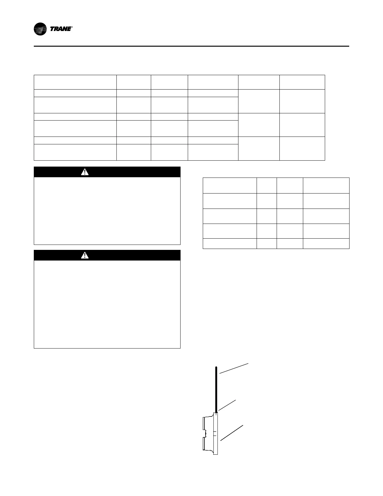
Figure 31. Waterbox lifting
Connection Device
Cables, Chains or Slings
Waterbox
Maintenance