50/60 Hz earth (ground) loops
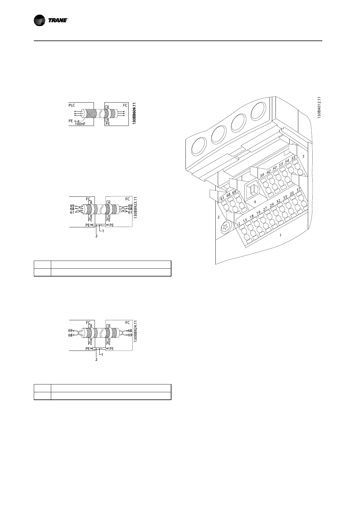
With very long control cables, earth loops (ground loops)
may occur. To eliminate earth (ground) loops, connect one
end of the screen-to-earth (ground) with a 100 nF
capacitor (keeping leads short).
Illustration 2.26
Avoid EMC noise on serial communication
This terminal is connected to earth (ground) via an internal
RC link. Use twisted-pair cables to reduce interference
between conductors. The recommended method is shown
below:
Illustration 2.27
1
Min. 16 mm
2
2Equalizing cable
Table 2.9
Alternatively, the connection to terminal 61 can be
omitted:
Illustration 2.28
1
Min. 16 mm
2
2Equalizing cable
Table 2.10
2.5.4 Control Terminal Types
Terminal functions and default settings are summarized in
2.5.6 Control Terminal Functions.
Illustration 2.29 Control Terminal Locations
•
Connector 1 provides four programmable digital
input terminals, two additional digital terminals
programmable as either input or output, a 24 V
DC terminal supply voltage, and a common for
optional customer supplied 24 V DC voltage
•
Connector 2 terminals (+)68 and (-)69 are for an
RS-485 serial communications connection
•
Connector 3 provides two analog inputs, one
analog output, 10 V DC supply voltage, and
commons for the inputs and output
•
Connector 4 is a USB port available for use with
the Trane Drive Utility (TDU)
•
Also provided are two Form C relay outputs that
are in various locations depending upon the
frequency converter configuration and size
•
Some options available for ordering with the unit
may provide additional terminals. See the manual
provided with the equipment option
Installation TR200 D-Frame Operating Instructions
28
BAS-SVX54B-EN


 To Next Page