connecting a motor to the frequency converter, always use
screened motor cable.
Cable Screened twisted pair (STP)
Impedance
120
Ω
Max. cable length 1200 m (including drop lines)
500 m station-to-station
Table 2.11
2.7 Optional Equipment
2.7.1 Load Share Terminals
Load share terminals enable the connection of the DC
circuits of several frequency converters. Load share
terminals are available in IP20 frequency converters and
extend out the top of the frequency converter. A terminal
cover, supplied with the frequency converter, must be
installed to maintain the IP20 rating of the enclosure.
Illustration 2.32 shows both the covered and uncovered
terminals.
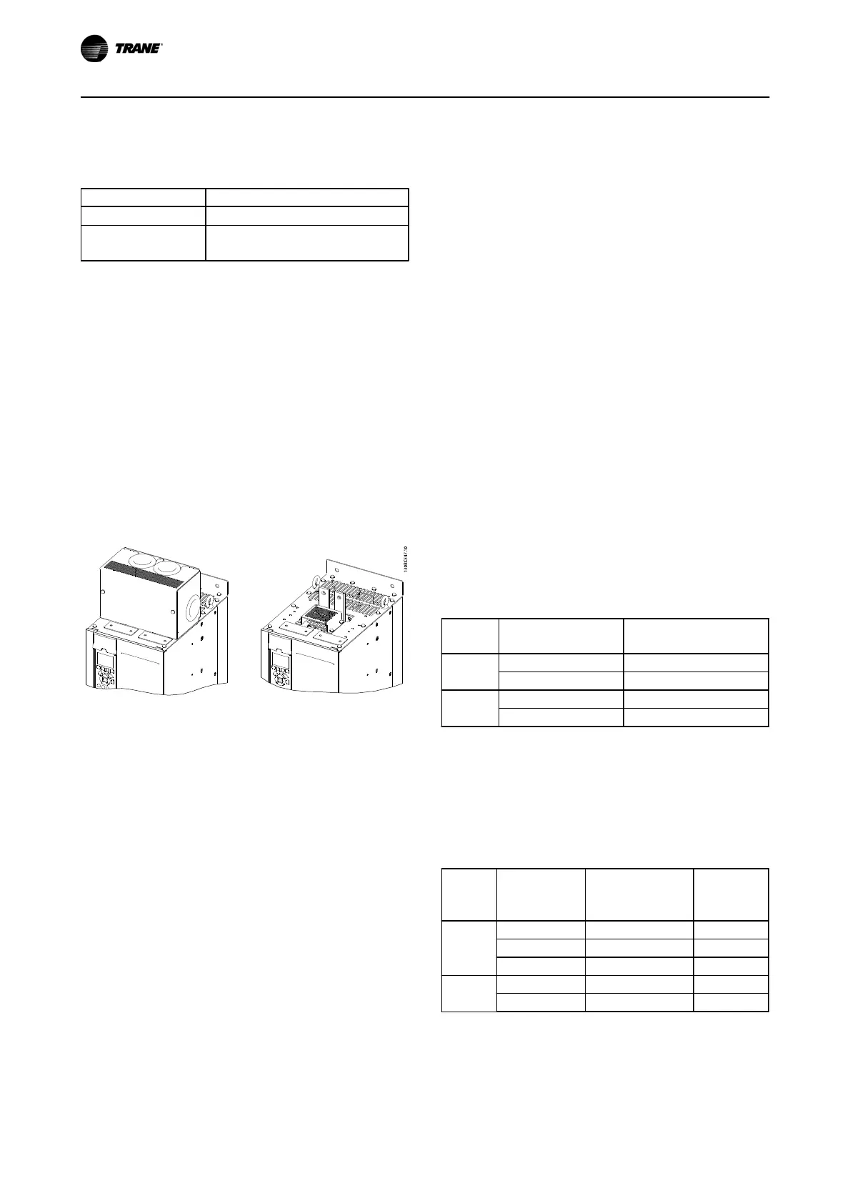
Illustration 2.32 Load Share or Regeneration Terminal with Cover
(L) and without Cover (R)
2.7.2 Regeneration Terminals
Regen (regeneration) terminals can be supplied for
applications that have a regenerative load. A regenerative
unit, supplied by a third party, connects to the regen
terminals so that power can be regenerated back onto the
mains, resulting in energy savings. Regen terminals are
available in IP20 frequency converters and extend out the
top of the frequency converter. A terminal cover, supplied
with the frequency converter, must be installed to
maintain the IP20 rating of the enclosure. Illustration 2.32
shows both the covered and uncovered terminals.
2.7.3 Anti-condensation Heater
An anti-condensation heater can be installed inside the
frequency converter to prevent condensation from forming
inside the enclosure when the unit is turned off. The
heater is controlled by customer-supplied 230 V AC. For
best results, operate the heater only when the unit is not
running and turn the heater off when the unit is running.
2.7.4 Brake Chopper
A brake chopper can be supplied for applications that
have a regenerative load. The brake chopper connects to a
brake resistor, which consumes the braking energy,
preventing an overvoltage fault on the DC bus. The
braking chopper is automatically activated when the DC
bus voltage exceeds a specified level, depending on the
nominal voltage of the frequency converter.
2.7.5 Mains Shield
The mains shield is a Lexan cover installed inside the
enclosure to provide protection according to VBG-4
accident-prevention requirements.
2.7.6 Mains Disconnect
The disconnect option is available in both varieties of
option cabinets. The position of the disconnect changes
based on the size of the options cabinet and whether or
not other options are present. Table 2.12 provides more
detail about which disconnects are used.
Voltage Frequency converter
model
Disconnect manufacturer
and type
380–500 V N110T5–N160T4 ABB OT400U03
N200T5–N315T4 ABB OT600U03
525–690 V N75KT7–N160T7 ABB OT400U03
N200T7–N400T7 ABB OT600U03
Table 2.12
2.7.7 Contactor
The contactor is powered by a customer-supplied 230 V
AC 50/60 Hz signal.
Voltage Frequency
converter model
Contactor
manufacturer and
type
IEC utilization
category
380-500 V N110T5–N160T4 GE CK95BE311N AC-3
N200T5–N250T4 GE CK11CE311N AC-3
N315T4 GE CK11CE311N AC-1
525-690 V N75KT7–N160T7 GE CK95BE311N AC-3
N200T7–N400T7 GE CK11CE311N AC-3
Table 2.13
Installation TR200 D-Frame Operating Instructions
30
BAS-SVX54B-EN