1.1.2 Extended Options Cabinets
If a frequency converter is ordered with one of the
following options, it is supplied with an options cabinet
that makes it taller.
•
Brake chopper
•
Mains disconnect
•
Contactor
•
Mains disconnect with contactor
•
Circuit breaker
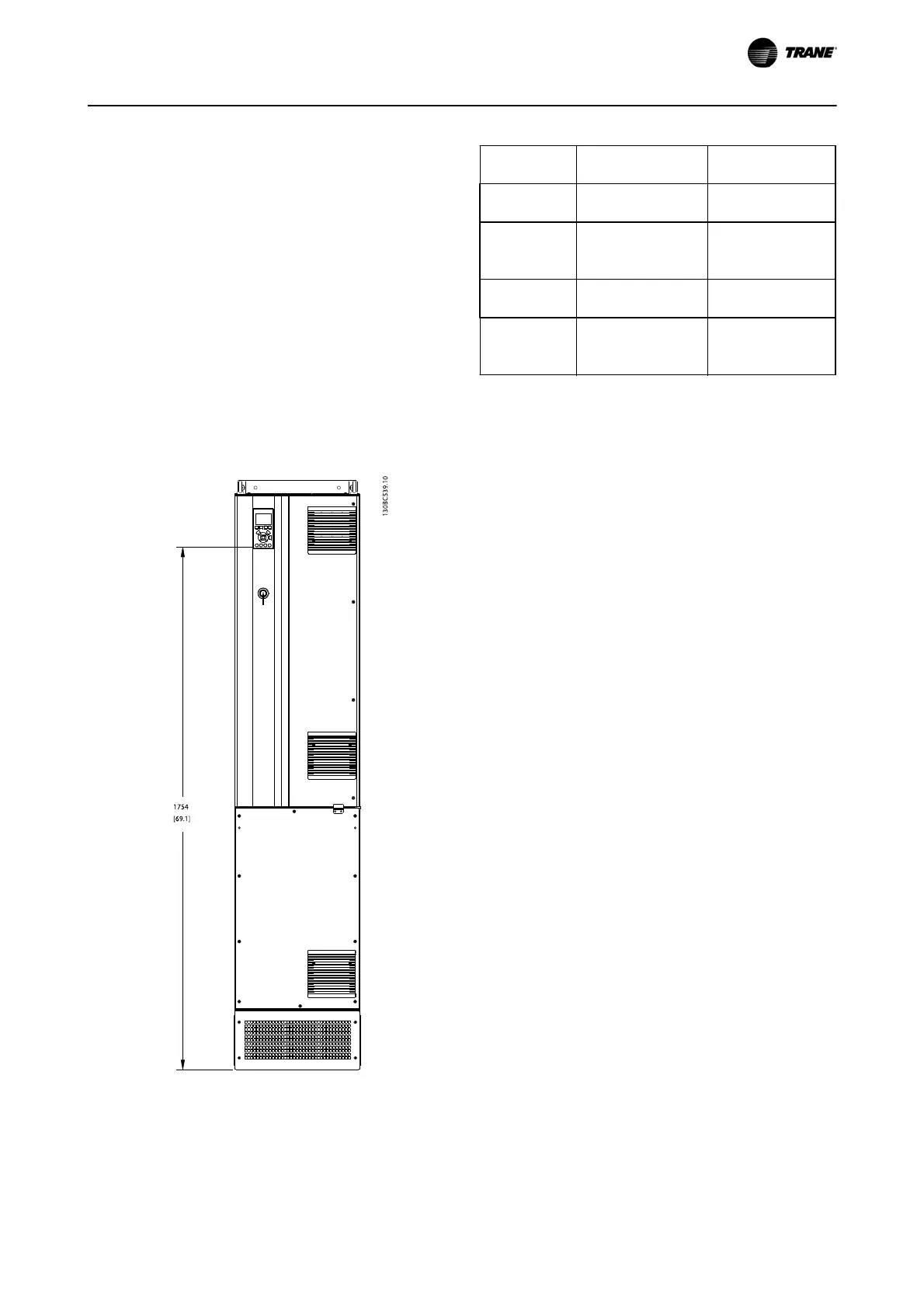
Illustration 1.3 shows an example of a frequency converter
with an options cabinet. Table 1.2 lists the variants for the
frequency converters that include input options.
Illustration 1.3 D7h Enclosure
Options unit
designations
Extension cabinets Possible options
D5h D1h enclosure with
short extension
Brake, Disconnect
D6h D1h enclosure with tall
extension
Contactor, Contactor
with Disconnect,
Circuit Breaker
D7h D2h enclosure with
short extension
Brake, Disconnect
D8h D2h enclosure with tall
extension
Contactor, Contactor
with Disconnect,
Circuit Breaker
Table 1.2
The D7h and D8h frequency converters (D2h plus options
cabinet), include a 200 mm pedestal for floor mounting.
There is a safety latch on the front cover of the options
cabinet. If the frequency converter is supplied with a mains
disconnect or circuit breaker, the safety latch prevents the
cabinet door from being opened while the frequency
converter is energized. Before opening the door of the
frequency converter, the disconnect or circuit breaker must
be opened (to de-energize the frequency converter) and
the cover of the options cabinet must be removed.
For frequency converters purchased with a disconnect,
contactor or circuit breaker, the name plate label includes
a type code for a replacement that does not include the
option. If there is a problem with the frequency converter,
it is replaced independent of the options.
Refer to 2.7 Optional Equipment for more detailed
descriptions of the input options and other options that
may be added to the frequency converter.
1.2 Purpose of the Manual
This manual is intended to provide detailed information for
the installation and start up of the frequency converter.
Chapter 2 Installation provides requirements for mechanical
and electrical installation, including input, motor, control
and serial communications wiring and control terminal
functions. Chapter 3 Start Up and Commissioning provides
detailed procedures for start up, basic operational
programming, and functional testing. The remaining
chapters provide supplementary details. These details
include user interface, detailed programming, application
examples, start-up troubleshooting, and specifications.
TR200 D-Frame Operating Instructions Introduction
BAS-SVX54B-EN
5