1Introduction
1.1 Product Overview
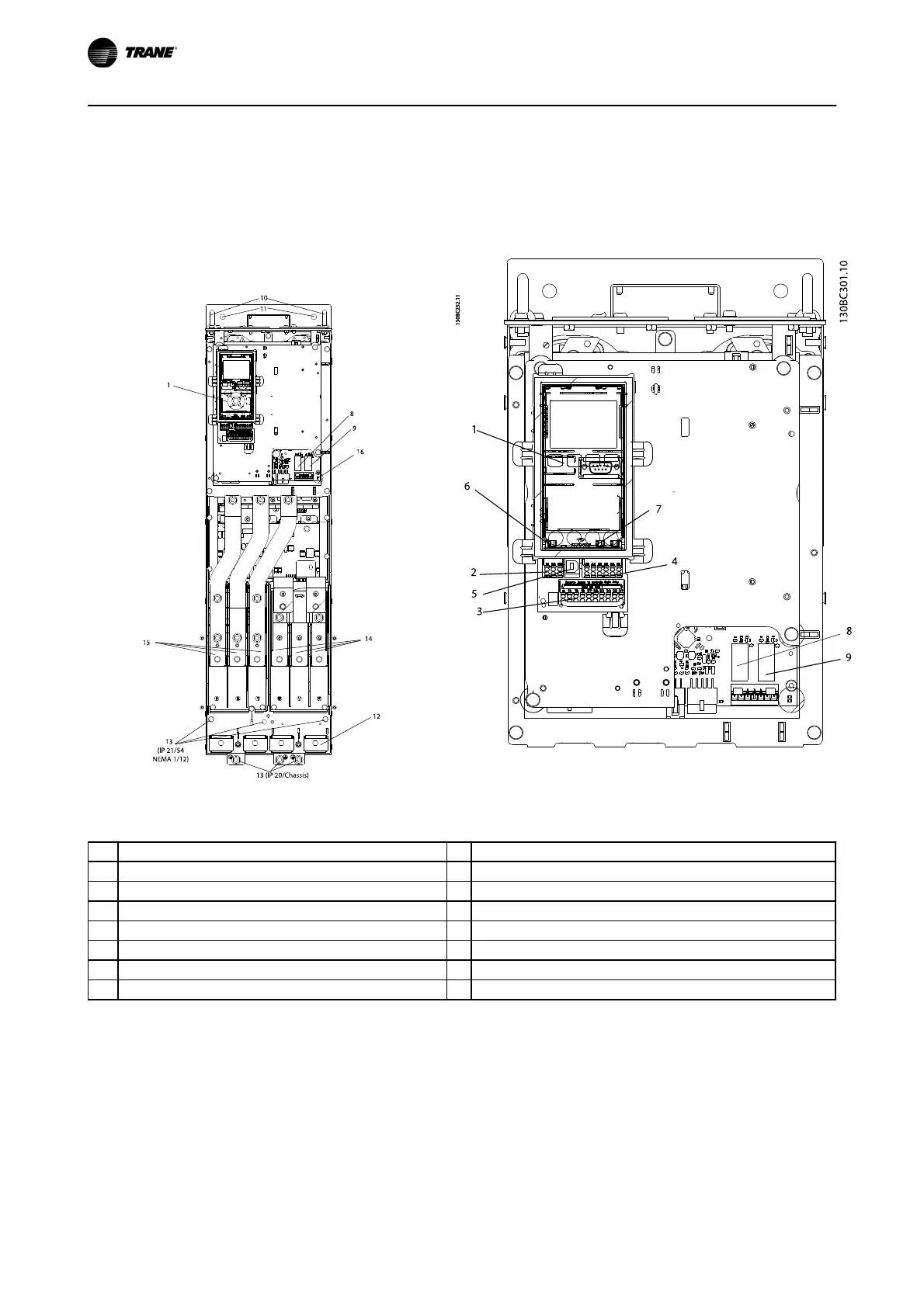
1.1.1 Interior Views
Illustration 1.1 D1 Interior Components
Illustration 1.2 Close-up View: LCP and Control Functions
1 LCP (Local Control Panel) 9 Relay 2 (04, 05, 06)
2 RS-485 serial bus connector 10 Lifting ring
3 Digital I/O and 24 V power supply 11 Mounting slot
4 Analog I/O connector 12 Cable clamp (PE)
5 USB connector 13 Earth (ground)
6 Serial bus terminal switch 14 Motor output terminals 96 (U), 97 (V), 98 (W)
7 Analog switches (A53), (A54) 15 Mains input terminals 91 (L1), 92 (L2), 93 (L3)
8 Relay 1 (01, 02, 03) 16 TB5 (IP21/54 only). Terminal block for anti-condensation heater
Table 1.1
NOTE
For location of TB6 (terminal block for contactor), see
2.4.3.2 Terminal Locations: D5h-D8h.
Introduction TR200 D-Frame Operating Instructions
4
BAS-SVX54B-EN