Chapter 7 Troubleshooting
36 CNT-SVX09B-EN
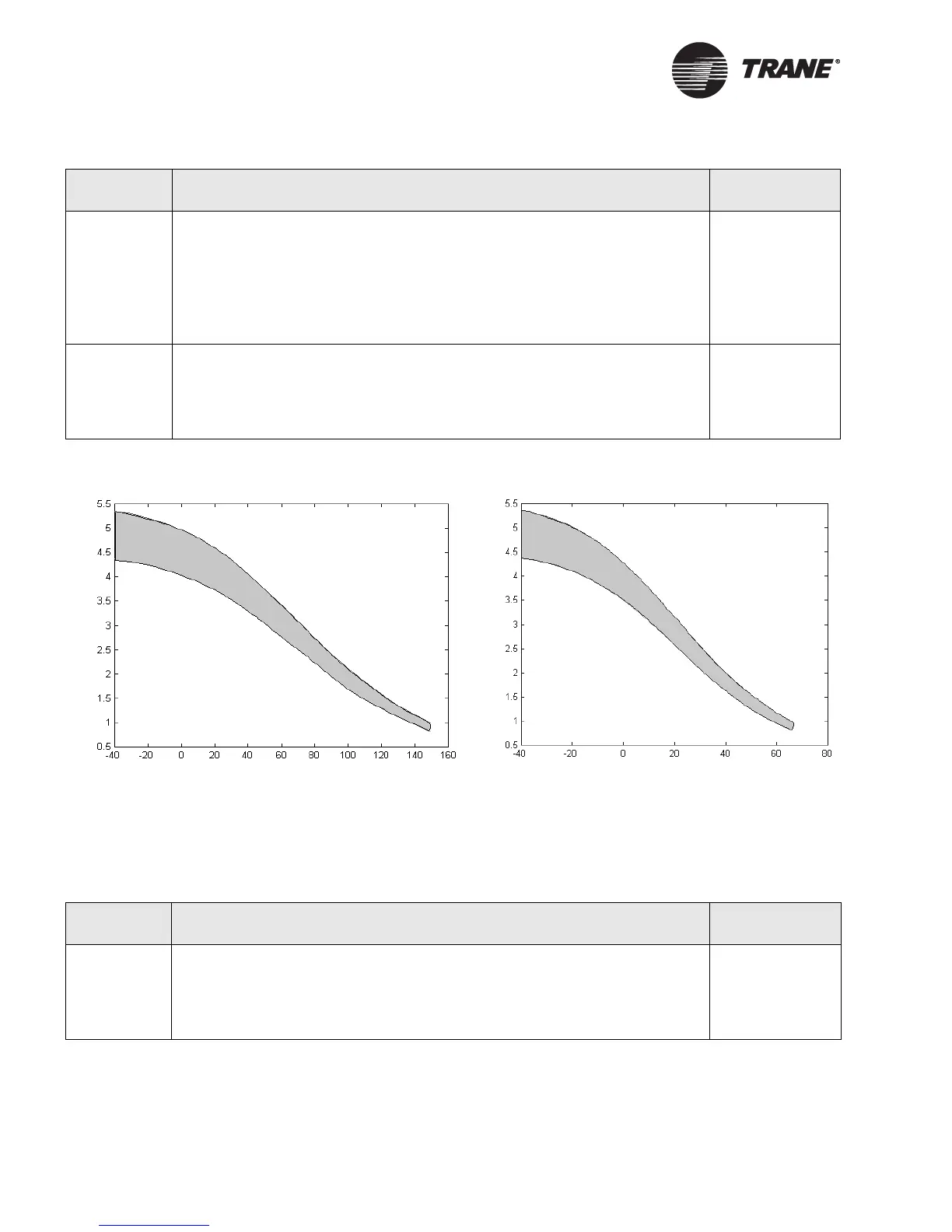
Figure 11. Voltage measured across terminals vs. temperature
Figure Note:
The correct region is shown in gray. A range of measurements is shown due to the variability of reference voltages
and thermistors.
Table 18. Universal input troubleshooting with a thermistor input
Step number Action Probable cause
Step 1 After following the steps in Table 17 on page 35, use your meter (set to read dc
voltage) to measure the voltage across the terminals for the input you are trou-
bleshooting. Verify the voltage falls into the gray area of the curve in Figure 11
for the current temperature.
If the voltage reading is not appropriate for the current temperature, you have
a sensor wiring problem.
If the voltage is correct for the current temperature, proceed to the next step.
Sensor wiring
problem
Step 2 Disconnect the sensor wires from the input terminals. Use your meter (set to
read dc voltage) to measure the voltage across the terminals for the input you
are troubleshooting.
The voltage should be 4.75–5.25 Vdc (see Table 22 on page 38). If the voltage is
not in that range, the Tracer MP503 has a circuit board problem.
Circuit board
problem
Table 19. Universal input troubleshooting with a binary input
Step number Action Probable cause
Step 1 After following the steps in Table 17 on page 35, disconnect the sensor wires
from the input terminals. Use your meter (set to read dc voltage) to measure
the voltage across the terminals for the input you are troubleshooting.
The voltage should be 16.00–18.00 Vdc (see Table 22 on page 38). If the voltage
is not in that range, the Tracer MP503 has a circuit board problem.
Circuit board
problem
Voltage (Vdc)
Voltage (Vdc)
Temperature (
o
F)
Temperature (
o
C)

 Loading...


