Universal input troubleshooting
CNT-SVX09B-EN 37
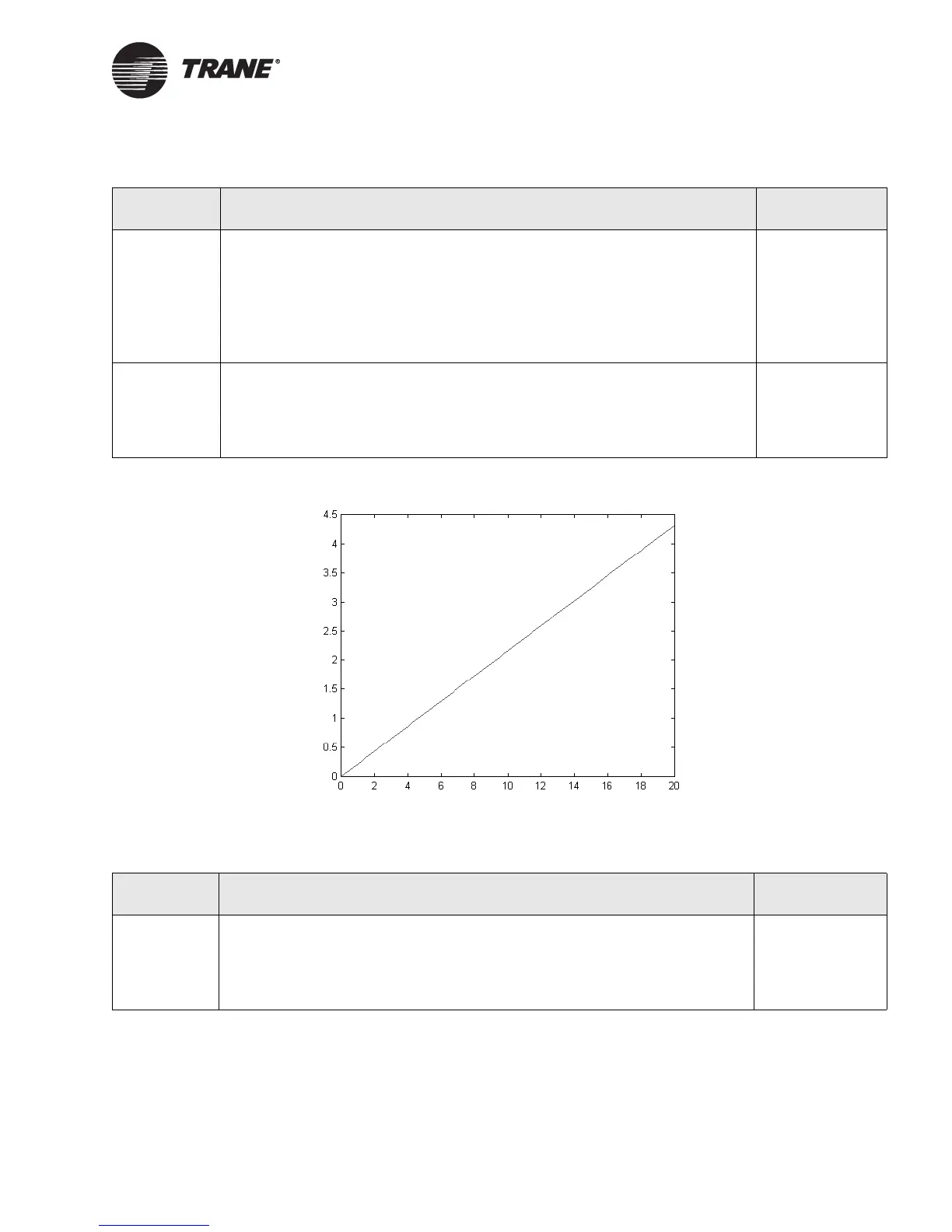
Figure 12. Voltage measured across terminals vs. input current
Table 20. Universal input troubleshooting with a 0–20 mA input
Step number Action Probable cause
Step 1 After following the steps in Table 17 on page 35, use your meter (set to read dc
voltage) to measure the voltage across the terminals for the input you are
troubleshooting. Verify the voltage falls on the curve shown in Figure 12 for
the input current.
If the voltage is not appropriate for the mA reading, you have a sensor wiring
problem.
If the voltage is correct for the mA reading, proceed to the next step.
Sensor wiring
problem
Step 2 Disconnect the sensor wires from the input terminals. Use your meter (set to
read dc voltage) to measure the voltage across the terminals for the input you
are troubleshooting.
The voltage should be 0.10–0.13 Vdc (see Table 22 on page 38). If the voltage is
not in that range, the Tracer MP503 has a circuit board problem.
Circuit board
problem
Table 21. Universal input troubleshooting with a 0–10 Vdc input
Step number Action Probable cause
Step 1 After following the steps in Table 17 on page 35, disconnect the sensor wires
from the input terminals. Use your meter (set to read dc voltage) to measure
the voltage across the terminals for the input you are troubleshooting.
The voltage should be 3.1–3.8 Vdc (see Table 22 on page 38). If the voltage is
not in that range, the Tracer MP503 has a circuit board problem.
Circuit board
problem
Current (mA)
Voltage (Vdc)

 Loading...


